Difference between revisions of "Manuals:MB Plus:Preliminary steps"
Shornstein (talk | contribs) |
Shornstein (talk | contribs) |
||
| (22 intermediate revisions by the same user not shown) | |||
| Line 1: | Line 1: | ||
| − | |||
<translate> | <translate> | ||
<!--T:1--> | <!--T:1--> | ||
{{DISPLAYTITLE: Preliminary steps|noerror}} | {{DISPLAYTITLE: Preliminary steps|noerror}} | ||
{{TOC_MBPlus}} | {{TOC_MBPlus}} | ||
| + | __TOC__ | ||
==Mounting the Microbeast PLUS unit== <!--T:2--> | ==Mounting the Microbeast PLUS unit== <!--T:2--> | ||
| − | Attach the Microbeast PLUS unit by using one of the provided 3M® gyropads at a preferably low vibrating position on your helicopter such as the gyro platform or receiver platform. You may need to choose another type of mounting pad depending on the vibration pattern of your helicopter. For more information please ask you Microbeast PLUS dealer.< | + | Attach the Microbeast PLUS unit by using one of the provided 3M® gyropads at a preferably low vibrating position on your helicopter such as the gyro platform or receiver platform. You may need to choose another type of mounting pad depending on the vibration pattern of your helicopter. For more information please ask you Microbeast PLUS dealer. |
| + | <p> | ||
| + | The MICROBEAST PLUS unit can be attached '''flat or upright''' on the helicopter. However, the '''servo connector pins must always point towards the front or rear''' of the helicopter. The small white sensor pinboard on the side must always be inline with flight direction.</p> | ||
<br /> | <br /> | ||
| − | + | <div class="noprint"> | |
| − | < | + | <gallery widths="400" heights="250" mode="nolines"> |
| − | + | Image:450 flat.jpg | |
| − | </ | + | Image:450 upright.jpg |
| − | < | + | </gallery> |
| − | < | + | </div> |
| − | + | <div class="onlyinprint"> | |
| − | + | {| | |
| − | < | + | |[[Image:450 flat.jpg|x200px]] |
| − | Pay attention that the edges of the Microbeast PLUS unit are all parallel with the corresponding rotational axes of the helicopter! Especially make sure that the mounting platform is perpendicular to the main shaft! On the other hand it is not important that the unit is directly placed on the rotation axis (which is nearly impossible).< | + | |[[Image:450 upright.jpg|x200px]] |
| − | + | |} | |
| − | + | </div> | |
| − | + | {{NL}} | |
| − | + | <p> | |
| − | + | '''Pay attention that the edges of the Microbeast PLUS unit are all parallel with the corresponding rotational axes of the helicopter!''' Especially make sure that the mounting platform is perpendicular to the main shaft! On the other hand it is not important that the unit is directly placed on the rotation axis (which is nearly impossible).</p> | |
| − | |||
| − | |||
| − | |||
<br /> | <br /> | ||
| + | <div class="noprint"> | ||
| + | <gallery widths="500" heights="250" mode="nolines" style="padding:5px 130px; "> | ||
| + | Image:Mounting_trex500.jpg | ||
| + | </gallery> | ||
| + | </div> | ||
| + | <div class="onlyinprint"> | ||
| + | {| | ||
| + | |[[Image:Blank_30.png|left]] | ||
| + | |[[Image:Mounting_trex500.jpg]] | ||
| + | |} | ||
| + | [[Image:Blank.png|none]] | ||
| + | </div> | ||
| + | {{NL}} | ||
| + | <p> | ||
| + | '''There are eight possible mounting orientations:''' | ||
<gallery mode="nolines" widths=200px> | <gallery mode="nolines" widths=200px> | ||
File:orient1.jpg|flat, cover on top, servo connectors showing to front | File:orient1.jpg|flat, cover on top, servo connectors showing to front | ||
| Line 33: | Line 47: | ||
File:orient4.jpg|upright, button on bottom, servo connectors showing to front | File:orient4.jpg|upright, button on bottom, servo connectors showing to front | ||
</gallery> | </gallery> | ||
| − | |||
<gallery mode="nolines" widths=200px> | <gallery mode="nolines" widths=200px> | ||
File:orient5.jpg|flat, cover on top, servo connectors showing to rear | File:orient5.jpg|flat, cover on top, servo connectors showing to rear | ||
| Line 40: | Line 53: | ||
File:orient8.jpg|upright, button on bottom, servo connectors showing to rear | File:orient8.jpg|upright, button on bottom, servo connectors showing to rear | ||
</gallery> | </gallery> | ||
| − | < | + | </p> |
| + | {{NL}} | ||
==Preparing the transmitter== <!--T:3--> | ==Preparing the transmitter== <!--T:3--> | ||
| − | You can use nearly any transmitter that provides at least 6 channels. By default 5 channels are used for controlling Microbeast PLUS and one channel controls the motor. If using additional features like AttitudeControl or | + | You can use nearly any transmitter that provides at least 6 channels. By default 5 channels are used for controlling Microbeast PLUS and one channel controls the motor. If using additional features like AttitudeControl or RPM Governor more channels may be useful to have. (Please note the RPM Governor only can be used if you have a [[Manuals:MB_Plus:Receiver_Installation/en#Single-Line_receivers|single-line receiver]]!).<br /> |
| + | {{NL}} | ||
| + | '''Create a new model in your radio‘s model memory.''' | ||
| + | <p> | ||
| + | {|class="gallery" style="font-style: italic" | ||
| + | |- | ||
| + | |width="200pt" style="padding:0px 10px;" align="center"|[[Image:SPM_0061.png|192px|none|border]] | ||
| + | |width="200pt" style="padding:0px 10px;" align="center"|[[Image:SPM_0064.png|192px|none|border]] | ||
| + | |width="200pt" style="padding:0px 10px;" align="center"|[[Image:SPM_0060.png|192px|none|border]] | ||
| + | |}<br /> | ||
| + | </p> | ||
<br /> | <br /> | ||
| − | + | '''Disable any mixing functions for the swashplate or rudder. Each function should be assigned to just one receiver channel.''' It is advisable to create different flight modes for different flight states/rotor headspeeds. This will allow to set tail gyro gain depending on the flight modes using the radio's tail gyro adjustment menu. | |
| + | <p> | ||
| + | {|class="gallery" style="font-style: italic" | ||
| + | |- | ||
| + | |width="200pt" style="padding:0px 10px;" align="center"|[[Image:SPM_0062.png|192px|none|border]] | ||
| + | |width="200pt" style="padding:0px 10px;" align="center"|[[Image:SPM_0067.png|192px|none|border]] | ||
| + | |}<br /> | ||
| + | </p> | ||
{{QUOTE|'''Never enable your radio‘s eCCPM mixing function!''' All the swashplate mixing will be done by Microbeast PLUS. Always set your radio‘s swash mixer to mCCPM (mechanical mixing) which is often called “H1”, “1 servo” or “normal“ mixing or disable “swash mixing” if applicable.}} | {{QUOTE|'''Never enable your radio‘s eCCPM mixing function!''' All the swashplate mixing will be done by Microbeast PLUS. Always set your radio‘s swash mixer to mCCPM (mechanical mixing) which is often called “H1”, “1 servo” or “normal“ mixing or disable “swash mixing” if applicable.}} | ||
| + | <br /> | ||
<!--T:4--> | <!--T:4--> | ||
| − | Be sure that all trims and sub trims are disabled and that all servo travels are set to 100%. Increasing or decreasing the servo travel/stick throw for aileron, elevator and rudder will later adjust the (maximum) control rates. For the moment to setup Microbeast PLUS let anything stay at default. Also do not adjust the collective pitch curve at the moment. For the setup procedures it has to be set as a straight line reaching from -100% to +100% (or 0 to 100% depending on radio brand). | + | {{NL}} |
| + | '''Be sure that all trims and sub trims are disabled and that all servo travels are set to 100%.''' Increasing or decreasing the servo travel/stick throw for aileron, elevator and rudder will later adjust the (maximum) control rates. For the moment to setup Microbeast PLUS let anything stay at default. Also do not adjust the collective pitch curve at the moment. For the setup procedures it has to be set as a straight line reaching from -100% to +100% (or 0 to 100% depending on radio brand). There mustn't be any active mixing functions (for example rudder revo-mixing). Have a look at the radio’s servo monitor: each stick has to control one channel/servo output (except for thrust stick which typically controls collective pitch and motor). Remember when using Microbeast PLUS you do not directly control the servos of the helicopter. By moving a stick you give a control command to the Microbeast PLUS unit which then performs the necessary servo movements to move the helictoper in the commanded direction. Each control command is bound to one servo output channel of the transmitter. When using flight modes again make sure that there is no mixing active in any flight mode and that all trims and subtrims are zero in all flight modes. | ||
<br /> | <br /> | ||
| − | + | {|class="gallery" style="font-style: italic" | |
| + | |- | ||
| + | |width="200pt" style="padding:0px 10px;" align="center"|[[Image:SPM_0095.png|192px|none|border]] | ||
| + | |width="200pt" style="padding:0px 10px;" align="center"|[[Image:SPM_0080.png|192px|none|border]] | ||
| + | |width="200pt" style="padding:0px 10px;" align="center"|[[Image:SPM_0081.png|192px|none|border]] | ||
| + | |}<br /> | ||
| + | {|class="gallery" style="font-style: italic" | ||
| + | |- | ||
| + | |width="600pt" style="padding:0px 30px;" align="center"|[[Image:Other_functions.png|192px|none|border]] | ||
| + | |}<br /> | ||
| + | {{NL}} | ||
| + | <p> | ||
| + | '''Other functions such as throttle curves, ESC switches or auxiliary functions can be adjusted as usual.''' When using the RPM Governor function the throttle adjustment will be described later. Also the switch assignment for AttitudeControl will be discussed at the specific topic.</p> | ||
<br /> | <br /> | ||
| − | |||
{{QUOTE|[[File:Warning.png|18px|sub]] '''Always make sure that the motor in electric models can not start when doing the adjustment work!''' If the drive battery is used as power supply for receiver, servos and Microbeast PLUS, disconnect the motor from the ESC.}} | {{QUOTE|[[File:Warning.png|18px|sub]] '''Always make sure that the motor in electric models can not start when doing the adjustment work!''' If the drive battery is used as power supply for receiver, servos and Microbeast PLUS, disconnect the motor from the ESC.}} | ||
</translate> | </translate> | ||
Latest revision as of 11:06, 18 March 2016
Mounting the Microbeast PLUS unit
Attach the Microbeast PLUS unit by using one of the provided 3M® gyropads at a preferably low vibrating position on your helicopter such as the gyro platform or receiver platform. You may need to choose another type of mounting pad depending on the vibration pattern of your helicopter. For more information please ask you Microbeast PLUS dealer.
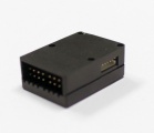
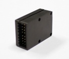
The MICROBEAST PLUS unit can be attached flat or upright on the helicopter. However, the servo connector pins must always point towards the front or rear of the helicopter. The small white sensor pinboard on the side must always be inline with flight direction.

|

|
Pay attention that the edges of the Microbeast PLUS unit are all parallel with the corresponding rotational axes of the helicopter! Especially make sure that the mounting platform is perpendicular to the main shaft! On the other hand it is not important that the unit is directly placed on the rotation axis (which is nearly impossible).

|
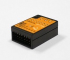
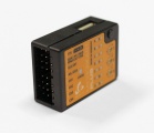
There are eight possible mounting orientations:
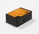
flat, cover on top, servo connectors showing to front
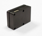
upright, button on top, servo connectors showing to front

flat, cover showing to bottom, servo connectors showing to front

upright, button on bottom, servo connectors showing to front


flat, cover on top, servo connectors showing to rear
upright, button on top, servo connectors showing to rear
flat, cover showing to bottom, servo connectors showing to rear
upright, button on bottom, servo connectors showing to rear


Preparing the transmitter
You can use nearly any transmitter that provides at least 6 channels. By default 5 channels are used for controlling Microbeast PLUS and one channel controls the motor. If using additional features like AttitudeControl or RPM Governor more channels may be useful to have. (Please note the RPM Governor only can be used if you have a single-line receiver!).
Create a new model in your radio‘s model memory.
 |
 |
 |
Disable any mixing functions for the swashplate or rudder. Each function should be assigned to just one receiver channel. It is advisable to create different flight modes for different flight states/rotor headspeeds. This will allow to set tail gyro gain depending on the flight modes using the radio's tail gyro adjustment menu.
 |
 |
Never enable your radio‘s eCCPM mixing function! All the swashplate mixing will be done by Microbeast PLUS. Always set your radio‘s swash mixer to mCCPM (mechanical mixing) which is often called “H1”, “1 servo” or “normal“ mixing or disable “swash mixing” if applicable.
Be sure that all trims and sub trims are disabled and that all servo travels are set to 100%. Increasing or decreasing the servo travel/stick throw for aileron, elevator and rudder will later adjust the (maximum) control rates. For the moment to setup Microbeast PLUS let anything stay at default. Also do not adjust the collective pitch curve at the moment. For the setup procedures it has to be set as a straight line reaching from -100% to +100% (or 0 to 100% depending on radio brand). There mustn't be any active mixing functions (for example rudder revo-mixing). Have a look at the radio’s servo monitor: each stick has to control one channel/servo output (except for thrust stick which typically controls collective pitch and motor). Remember when using Microbeast PLUS you do not directly control the servos of the helicopter. By moving a stick you give a control command to the Microbeast PLUS unit which then performs the necessary servo movements to move the helictoper in the commanded direction. Each control command is bound to one servo output channel of the transmitter. When using flight modes again make sure that there is no mixing active in any flight mode and that all trims and subtrims are zero in all flight modes.
 |
 |
 |
 |
Other functions such as throttle curves, ESC switches or auxiliary functions can be adjusted as usual. When using the RPM Governor function the throttle adjustment will be described later. Also the switch assignment for AttitudeControl will be discussed at the specific topic.
Always make sure that the motor in electric models can not start when doing the adjustment work! If the drive battery is used as power supply for receiver, servos and Microbeast PLUS, disconnect the motor from the ESC.