Manuals:MBPlusFblV5:Hardware Installation/en: Difference between revisions
Importing a new version from external source |
(No difference)
|
Revision as of 10:13, 13 November 2017
Attaching your Microbeast PLUS to the helicopter
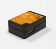
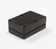
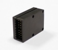
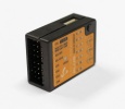
Attach the Microbeast PLUS unit by using one of the provided 3M® gyropads at a preferably low vibrating position on your helicopter such as the gyro platform or receiver platform. You may need to choose another type of mounting pad depending on the vibration pattern of your helicopter.
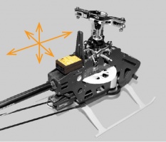
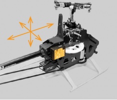
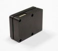
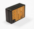
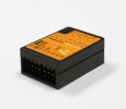
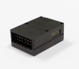
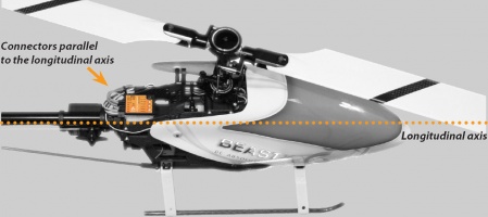
There are eight possible mounting orientations: The MICROBEAST PLUS unit either can be attached flat or upright on the helicopter and the servo connector pins must always point towards the front or rear of the helicopter. The small white sensor pinboard on the side must always be inline with flight direction:
Pay attention that the edges of the Microbeast PLUS unit are all parallel with the corresponding rotational axes of the helicopter! Especially make sure that the mounting platform is perpendicular to the main shaft! On the other hand it is not important that the unit is directly placed on the rotation axis (which is nearly impossible) and also it is not important whether the system is placed in parallel to the ground or not.
Introduction to MICROBEAST PLUS HD
MICROBEAST PLUS HD is the most powerful flybarless system from the MICROBEAST series. While function and operation are identical to MICROBEAST PLUS, the HD version is characterized by the possibility of a high power supply. This meets the requirements of speed flyers and extreme 3D pilots and is primarily used in helicopters larger than 500 size that have very power consuming servos installed. By using a low-resistance high-current connector system MICROBEAST PLUS HD makes it possible to use thick power cables for connecting receiver battery or BEC which preserves a virtually loss-free transfer of electric current. In addition the power connection is switchable using a particularly fail-safe switch system, so there is no need for a separate and costly power switch. Apart from the high power supply and the switch system the operation of MICROBEAST PLUS HD is identical to MICROBEAST PLUS. So it is not explicitly dealt with the HD version later on in this manual. All subsequent executions are also based on MICROBEAST PLUS HD!
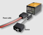
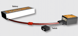
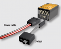
Solder to the supplied power cable a matching counterpart for the supply battery used or connect it with the BEC power wires (of your speed controller). When using a battery it is not recommended to directly connect the battery to the MICROBEAST PLUS HD without using the supplied power cable as an adapter. Continuous plugging and unplugging can cause the overlying servo plugs getting unplugged accidentally or cause the adhesive gyro pad to get loose! Receiver and servo plugs are connected to the ports on top of the unit. There is no difference between HD and non HD version in this respect.
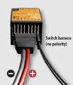
The use of the electronic switching system is optional. The switch is designed in a way so that it interrupts the power circuit by shorting the switch circuit in OFF position. If the switch is not connected MICROBEAST PLUS HD is switched on permanently as soon as the power is connected.
Please note:
- Using the high power connection port is not a must. You can also use MICROBEAST PLUS HD in a conventional manner by powering the unit from the receiver ports in the top row, as shown in the chapter on receiver installation. However, using the electronic power switch system is not possible then!
- The electrical connections of the high power connection port and the upper terminal row form a parallel power circuit during operation. So it is possible to connect an additional power source at the upper terminal row. For example this can be a buffering battery or a backup system that shall protect against failure of the primary power source. In this case note the manufacturer‘s instructions, if this is possible and permissible for the supply systems used. Also note that using the electronic power switch system of MICROBEAST PLUS HD is not possible in this combination!
- Note that the system can only be as powerful as the power source allows. Use power cables with sufficient diameter, avoid long cable length and only use a plug system for connection of battery and power cable that is capable of transferring high currents.
- MICROBEAST PLUS HD does not supply an internal voltage regulation! The voltage that is applied to the high power connection port will directly be passed to the servo and receiver connections. Only use electronic components (servos and receiver) that are designed for your power source.
MICROBEAST PLUS HD will draw a very low amount of current even when the system is switched off! Therefore always completely disconnect the battery from the system if you do not use the model for a extended period of time to prevent the supply battery from getting discharged and damaged in consequence.
