Translations:Manuals:MBUltraFblV5:Radio System/14/en: Difference between revisions
Importing a new version from external source |
Importing a new version from external source |
||
| (2 intermediate revisions by the same user not shown) | |||
| Line 1: | Line 1: | ||
== Single wire with telemetry == | == Single wire with telemetry == | ||
Receivers with bidirectional telemetry uplink (Spektrum® SRXL2, Jeti® EXBUS, FRSKY® F.Port2, FUTABA® SBUS2) must be connected to the pin board at the side of MICROBEAST ULTRA. To connect a receiver with standard servo connectors, i.e. the SPEKTRUM® '''AR6610T''', '''AR8020T''' or JETI EXBUS receivers, you need an adapter from servo plug to JST-ZH type. We offer a special adapter if needed - order nr. BXA76403. Voltage is the first pin from the left, signal is connected at the third pin from the left. Minus is the second pin from the front/right.<br /> | Receivers with bidirectional telemetry uplink (Spektrum® SRXL2, Jeti® EXBUS, FRSKY® F.Port2, FUTABA® SBUS2) must be connected to the pin board at the side of MICROBEAST ULTRA. To connect a receiver with standard servo connectors, i.e. the SPEKTRUM® '''AR6610T''', '''AR8020T''' or JETI EXBUS receivers, you need an adapter from servo plug to JST-ZH type. We offer a special adapter if needed - order nr. BXA76403. Voltage is the first pin from the left, signal is connected at the third pin from the left. Minus is the second pin from the front/right.<br /> | ||
<br /> | |||
When using a Futaba receiver with SBUS2 output, it is necessary to connect a 4.7kOhms resistor between signal pin and "-" (minus), so called pull-down resistor. You can make you own connection wire, if you have some skills in soldering. Otherwise please ask you local dealer if he can help out with such a modified wire.<br /> | |||
<br /> | |||
{|cellspacing="50" style="text-align:center;" | {|cellspacing="50" style="text-align:center;" | ||
|[[Image:SRXL2 AR6610T en.png| x150px]] | |[[Image:SRXL2 AR6610T en.png| x150px]] | ||
| Line 16: | Line 19: | ||
| Modified 4-pin SRXL connector | | Modified 4-pin SRXL connector | ||
|} | |} | ||
{{WARNING_QUOTE|'''Never connect the 4-pin receiver connector to MICROBEAST ULTRA without modification and in wrong polarity! This will damage your receiver immediately!''' Check polarity at least twice before connecting the receiver to MICROBEAST ULTRA . It is up to you to make sure polarity is correct. We do not assume any liability in case you do it wrong.}} | {{WARNING_QUOTE|'''Never connect the 4-pin receiver connector to MICROBEAST ULTRA without modification and in wrong polarity! This will damage your receiver immediately!''' Check polarity at least twice before connecting the receiver to MICROBEAST ULTRA . It is up to you to make sure polarity is correct. We do not assume any liability in case you do it wrong.}} | ||
<br /> | <br /> | ||
<br /> | <br /> | ||
Latest revision as of 13:31, 23 March 2023
Single wire with telemetry
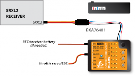
Receivers with bidirectional telemetry uplink (Spektrum® SRXL2, Jeti® EXBUS, FRSKY® F.Port2, FUTABA® SBUS2) must be connected to the pin board at the side of MICROBEAST ULTRA. To connect a receiver with standard servo connectors, i.e. the SPEKTRUM® AR6610T, AR8020T or JETI EXBUS receivers, you need an adapter from servo plug to JST-ZH type. We offer a special adapter if needed - order nr. BXA76403. Voltage is the first pin from the left, signal is connected at the third pin from the left. Minus is the second pin from the front/right.
When using a Futaba receiver with SBUS2 output, it is necessary to connect a 4.7kOhms resistor between signal pin and "-" (minus), so called pull-down resistor. You can make you own connection wire, if you have some skills in soldering. Otherwise please ask you local dealer if he can help out with such a modified wire.

|
| SRXL2 receiver with standard servo connector and adapter |
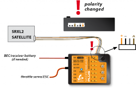
To connect a SRXL2 remote receiver like SPM4650/SPM4651T it is necessary to INTERCHANGE THE WIRES of the supplied 4-pin receiver connector. In this configuration you can directly plug in the receiver without the need for an extra adapter. But be very careful! Make sure plus and minus are placed properly! The signal wire is connected at the fourth pin from the front/right, minus ist second pin from the front/right, voltage (+3.3V) is the first pin from the front/right. On satellite side the signal output is on the outer side, the pin next to it is not used, then we have voltage and on the inner side comes minus.

|
|
| SRXL2 satellite receiver with modified satellite connector | Modified 4-pin SRXL connector |
Never connect the 4-pin receiver connector to MICROBEAST ULTRA without modification and in wrong polarity! This will damage your receiver immediately! Check polarity at least twice before connecting the receiver to MICROBEAST ULTRA . It is up to you to make sure polarity is correct. We do not assume any liability in case you do it wrong.