Manuals:MBUltraFblV5:Radio System: Difference between revisions
Shornstein (talk | contribs) No edit summary |
Shornstein (talk | contribs) No edit summary |
||
| (4 intermediate revisions by the same user not shown) | |||
| Line 38: | Line 38: | ||
* JETI® EXBUS | * JETI® EXBUS | ||
* GRAUPNER® HOTT | * GRAUPNER® HOTT | ||
* FRSKY® F. | * FRSKY® F.Port | ||
* FUTABA® SBUS2 | * FUTABA® SBUS2 | ||
<br /> | <br /> | ||
| Line 88: | Line 88: | ||
== Single wire with telemetry == <!--T:14--> | == Single wire with telemetry == <!--T:14--> | ||
Receivers with bidirectional telemetry uplink (Spektrum® SRXL2, Jeti® EXBUS, FRSKY® F.Port2, FUTABA® SBUS2) must be connected to the pin board at the side of MICROBEAST ULTRA. To connect a receiver with standard servo connectors, i.e. the SPEKTRUM® '''AR6610T''', '''AR8020T''' or JETI EXBUS receivers, you need an adapter from servo plug to JST-ZH type. We offer a special adapter if needed - order nr. BXA76403. Voltage is the first pin from the left, signal is connected at the third pin from the left. Minus is the second pin from the front/right.<br /> | Receivers with bidirectional telemetry uplink (Spektrum® SRXL2, Jeti® EXBUS, FRSKY® F.Port2, FUTABA® SBUS2) must be connected to the pin board at the side of MICROBEAST ULTRA. To connect a receiver with standard servo connectors, i.e. the SPEKTRUM® '''AR6610T''', '''AR8020T''' or JETI EXBUS receivers, you need an adapter from servo plug to JST-ZH type. We offer a special adapter if needed - order nr. BXA76403. Voltage is the first pin from the left, signal is connected at the third pin from the left. Minus is the second pin from the front/right.<br /> | ||
<br /> | |||
When using a Futaba receiver with SBUS2 output, it is necessary to connect a 4.7kOhms resistor between signal pin and "-" (minus), so called pull-down resistor. You can make you own connection wire, if you have some skills in soldering. Otherwise please ask you local dealer if he can help out with such a modified wire.<br /> | |||
<br /> | |||
{|cellspacing="50" style="text-align:center;" | {|cellspacing="50" style="text-align:center;" | ||
|[[Image:SRXL2 AR6610T en.png| x150px]] | |[[Image:SRXL2 AR6610T en.png| x150px]] | ||
| Line 103: | Line 106: | ||
| Modified 4-pin SRXL connector | | Modified 4-pin SRXL connector | ||
|} | |} | ||
{{WARNING_QUOTE|'''Never connect the 4-pin receiver connector to MICROBEAST ULTRA without modification and in wrong polarity! This will damage your receiver immediately!''' Check polarity at least twice before connecting the receiver to MICROBEAST ULTRA . It is up to you to make sure polarity is correct. We do not assume any liability in case you do it wrong.}} | {{WARNING_QUOTE|'''Never connect the 4-pin receiver connector to MICROBEAST ULTRA without modification and in wrong polarity! This will damage your receiver immediately!''' Check polarity at least twice before connecting the receiver to MICROBEAST ULTRA . It is up to you to make sure polarity is correct. We do not assume any liability in case you do it wrong.}} | ||
<br /> | <br /> | ||
<br /> | <br /> | ||
| Line 111: | Line 114: | ||
<br /> | <br /> | ||
Note that it is not possible to use the [SYS] port for communication with the StudioX app when the telemetry data wire is connected. Still you can access StudioX and configure your helicopter by app if you connect the USB2SYS/BLE2SYS interface to the [SYS] port before powering up the helicopter.<br /> | Note that it is not possible to use the [SYS] port for communication with the StudioX app when the telemetry data wire is connected. Still you can access StudioX and configure your helicopter by app if you connect the USB2SYS/BLE2SYS interface to the [SYS] port before powering up the helicopter.<br /> | ||
<br /> | |||
<br /> | <br /> | ||
| Line 122: | Line 126: | ||
== Single wire with telemetry == <!--T:19--> | == Single wire with telemetry == <!--T:19--> | ||
When using a telemetry receiver and an ESC with telemetry data connector, the ESC is connected to the '''[IO1]''' output. The telemetry data signal of the ESC is connected to '''[IO2]''' input. | When using a telemetry receiver and an ESC with telemetry data connector, the ESC is connected to the '''[IO1]''' output. The telemetry data signal of the ESC is connected to '''[IO2]''' input.<br /> | ||
<br /> | |||
Spektrum® AVIAN ESC do not have a separate line for telemetry data. Here motor control and telemetry data is sent bidirectional on the main connection wire. For this we must connect the AVIAN ESC to the [SYS] port of MICROBEAST ULTRA, as the other connectors [IO1] and [IO2] can only work in one direction.<br /> | |||
<br /> | |||
You will get further information about connecting and setting up the speed controller in a later section!<br /> | |||
<br /> | <br /> | ||
Latest revision as of 07:46, 22 June 2023
MICROBEAST ULTRA can work with a lot of different receiver types and radio brands, especially with different types of radio signal protocols. Depending on which signal protocol and receiver you intend to use, the wiring layout may vary. In the following you can see all supported protocols and specific wiring schemes for each receiver type.
![]() Ensure a tight fit of the connectors. The pin board of MICROBEAST ULTRA is designed so that the plugs firmly clamp each other when they are fully inserted. Anyhow, especially when using a receiver with single wire output it is possible that connectors are plugged in with no adjacent neighbors. Such plugs should additionally be secured against loosening.
Ensure a tight fit of the connectors. The pin board of MICROBEAST ULTRA is designed so that the plugs firmly clamp each other when they are fully inserted. Anyhow, especially when using a receiver with single wire output it is possible that connectors are plugged in with no adjacent neighbors. Such plugs should additionally be secured against loosening.
Standard receiver
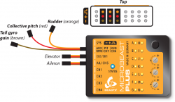
A receiver with multiple servo output connectors is what we consider a "Standard receiver". Here you connect each servo output to one control function of MICROBEAST ULTRA by using one wire for each function. The 5 control functions (wires) are: Aileron, Elevator, Rudder, Collective pitch and Gyro gain. If you don't know which stick controls which channel have a look at your radio's servo monitor, refer to your radios instruction manual or simply connect a servo to test what each output is used for!
|
Here we show connection layouts for two common radio brands. Note that this is only exemplary, you can use any radio system on the market, not only these two brands! Anyhow, make sure that you connect the wires to the correct functions as mentioned above.

|

|
- The wires for rudder, pitch and gyro are all signal wires. Although some have different color, they must be placed on the same receiver side as the the orange wires from aileron and elevator!
- You must connect all 5 functions/wires to the receiver. When you don't connect all wires, the system will not finish initialization sequence!
- The throttle servo/speed controller is connected to the receiver's throttle output. So using the headspeed governor function of MICROBEAST ULTRA is not possible in combination with a Standard receiver!
Receivers with single wire output
A single-line receiver transmits all control functions over one single connection wire to MICROBEAST ULTRA. This is done by packing all channel outputs into a digital data paket or by chaining the signals onto one line.
MICROBEAST ULTRA supports the following systems with telemetry uplink:
- Spektrum® SRXL2
- JETI® EXBUS
- GRAUPNER® HOTT
- FRSKY® F.Port
- FUTABA® SBUS2
MICROBEAST ULTRA supports the following systems without telemetry:
- Spektrum® DSMX/DSM2 remote receivers and receivers with SRXL output
- Futaba® SBUS
- Multiplex® SRXL
- JR® X-Bus (Mode B)
- Jeti® UDI
- ALIGN® and FlySky® iBus
- any SPPM receiver (serial ppm).
Single wire without telemetry
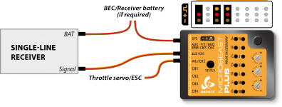
- The single-line connection wire is plugged into the [IO1] input of MICROBEAST ULTRA
- The throttle servo or ESC is connected to the [IO2] output. When using a speed controller with BEC, from here the power will be distributed to receiver and servos.
- You can connect a power supply (second BEC wire, battery) to the [SYS] port and/or to the receiver (in case this has additional servo or battery ports). All servo ports will form a parallel power circuit (except the port [RUD|PIT|AUX]; please do not connect anything here!).
|
| Single-line receiver with additional servo output channels |
![]() When using a big heli with standard size servos it may be insufficient to only provide power at the [SYS] port or receiver. Adding additional power wires is highly recommended! If there are no other ports left to additionally feed in power, we recommend using the MICROBEAST PLUS HD which comes witch an additional high power input. This reduces wiring resistance and serves todays demands for a robust servo power supply.
When using a big heli with standard size servos it may be insufficient to only provide power at the [SYS] port or receiver. Adding additional power wires is highly recommended! If there are no other ports left to additionally feed in power, we recommend using the MICROBEAST PLUS HD which comes witch an additional high power input. This reduces wiring resistance and serves todays demands for a robust servo power supply.
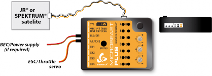
Remote receivers (Spektrum® DSMX/DSM2, JR® DMSS, ALIGN® iBus) can be directly connected to the white pin board at the side of MICROBEAST ULTRA. Here the receiver will be powered with a stabilized voltage of 3.3 Volts! Voltage is the first pin from the front/right, minus is the second pin from the right, signal is connected at the third pin from the right.
Please note: MICROBEAST ULTRA does not support connecting more than one remote satellite at a time!
|
| JR®/Spektrum® remote satellite connected at side pin board |
Using a remote satellite is only recommended for small rc models (helicopters of 450 size or smaller). Due to the design, one single receiving unit is more prone to radio interference and can result in reduced transmission range!
Single wire with telemetry
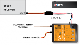
Receivers with bidirectional telemetry uplink (Spektrum® SRXL2, Jeti® EXBUS, FRSKY® F.Port2, FUTABA® SBUS2) must be connected to the pin board at the side of MICROBEAST ULTRA. To connect a receiver with standard servo connectors, i.e. the SPEKTRUM® AR6610T, AR8020T or JETI EXBUS receivers, you need an adapter from servo plug to JST-ZH type. We offer a special adapter if needed - order nr. BXA76403. Voltage is the first pin from the left, signal is connected at the third pin from the left. Minus is the second pin from the front/right.
When using a Futaba receiver with SBUS2 output, it is necessary to connect a 4.7kOhms resistor between signal pin and "-" (minus), so called pull-down resistor. You can make you own connection wire, if you have some skills in soldering. Otherwise please ask you local dealer if he can help out with such a modified wire.
|
| SRXL2 receiver with standard servo connector and adapter |
To connect a SRXL2 remote receiver like SPM4650/SPM4651T it is necessary to INTERCHANGE THE WIRES of the supplied 4-pin receiver connector. In this configuration you can directly plug in the receiver without the need for an extra adapter. But be very careful! Make sure plus and minus are placed properly! The signal wire is connected at the fourth pin from the front/right, minus ist second pin from the front/right, voltage (+3.3V) is the first pin from the front/right. On satellite side the signal output is on the outer side, the pin next to it is not used, then we have voltage and on the inner side comes minus.
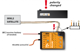
|
|
| SRXL2 satellite receiver with modified satellite connector | Modified 4-pin SRXL connector |
Never connect the 4-pin receiver connector to MICROBEAST ULTRA without modification and in wrong polarity! This will damage your receiver immediately! Check polarity at least twice before connecting the receiver to MICROBEAST ULTRA . It is up to you to make sure polarity is correct. We do not assume any liability in case you do it wrong.
Graupner HOTT telemetry
When using a Graupner HOTT receiver with telemetry uplink, the telemetry data line is connected to [SYS] port. The SUMD data signal for controlling the helicopter is connected at [IO1] port. Please make sure telemetry output is enabled on the receiver side. Usually you can do this from the telemetry menu in the transmitter. Please refer to instructions of the radio system for more information.
Note that it is not possible to use the [SYS] port for communication with the StudioX app when the telemetry data wire is connected. Still you can access StudioX and configure your helicopter by app if you connect the USB2SYS/BLE2SYS interface to the [SYS] port before powering up the helicopter.
Connecting throttle output
The electric speed controller (ESC) or throttle servo is connected at different locations depending on the receiver system used. With stanard receivers you must connect the ESC/servo directly at the receiver. With single wire receivers the ESC/servo is connected to MICROBEAST ULTRA.
Single wire without telemetry
When telemetry is not in use, the throttle servo or ESC is connected to the [IO2] output.
Single wire with telemetry
When using a telemetry receiver and an ESC with telemetry data connector, the ESC is connected to the [IO1] output. The telemetry data signal of the ESC is connected to [IO2] input.
Spektrum® AVIAN ESC do not have a separate line for telemetry data. Here motor control and telemetry data is sent bidirectional on the main connection wire. For this we must connect the AVIAN ESC to the [SYS] port of MICROBEAST ULTRA, as the other connectors [IO1] and [IO2] can only work in one direction.
You will get further information about connecting and setting up the speed controller in a later section!
Graupner HOTT telemetry
When using a Graupner HOTT receiver with telemetry uplink, the throttle servo or ESC is connected to the [IO2] output. The telemetry data signal of the ESC is connected at the side input of MICROBEAST ULTRA. Here "-" (minus) is the second pin from front and "S" (signal) is the third pin from front. "+" (plus) can be connected at the first pin from behind.
External power supply
You can connect a power supply (second BEC wire, battery) to the [SYS] port and/or to the receiver (in case this has additional servo or battery ports). All servo ports will form a parallel power circuit (except the port [RUD|PIT|AUX]; please do not connect anything here!).
When using a big heli with standard size servos it may be insufficient to only provide power at the [SYS] port or receiver. Adding additional power wires is highly recommended! If there are no other ports left to additionally feed in power, we recommend using the MICROBEAST PLUS HD which comes witch an additional high power input. This reduces wiring resistance and serves todays demands for a robust servo power supply.