Translations:Manuals:BXFbl:Radio Setup:RemoteSat/3/de: Difference between revisions

From BEASTX Wiki
Jump to navigation Jump to search
Created page with "= Anschlussschema = <br /> '''MICROBEAST PLUS / MICROBEAST ULTRA''<br /> Schließe den Satellitenempfänger an der Seite des MICROBEAST an. Der Anschluss erfolgt an den ersten..."
 
(No difference)

Latest revision as of 19:38, 20 May 2024

Information about message (contribute)
This message has no documentation. If you know where or how this message is used, you can help other translators by adding documentation to this message.
Message definition (Manuals:BXFbl:Radio Setup:RemoteSat)
= Connection scheme =
<br />
'''MICROBEAST PLUS / MICROBEAST ULTRA'''<br />
Connect the remote satellite at the side of your MICROBEAST. It must be connected at the first 3 pins from the right, when looking at the pin board from the side. Voltage is the first pin from the front/right, minus is the second pin from the right, signal is connected at the third pin from the right.<br />
<br />
{|cellspacing="20" style="text-align:center;"
|[[Image:Mbplus_spektrum_rx2.png | x150px]]
<!-- |[[Image:Spektrum_RX_Sat.png | x150px]] -->
|- style="text-align:center; font-size:75%;"
| JR®/Spektrum® remote satellite connected at side pin board
<!-- | JR®/Spektrum® remote satellite connection with power adapter -->
|}
<br />

Anschlussschema


'MICROBEAST PLUS / MICROBEAST ULTRA
Schließe den Satellitenempfänger an der Seite des MICROBEAST an. Der Anschluss erfolgt an den ersten 3 Pins von rechts, wenn man von der Seite auf das Pinboard blickt. Spannung ist der erste Pin von vorne/rechts, Minus ist der zweite Pin von rechts, Signal wird am dritten Pin von rechts angeschlossen.
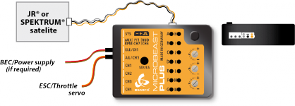
JR®/Spektrum® Satellitenanschluss am seitlichen Pinboard