Manuals:MBPlusFblV5:BankSwitch: Difference between revisions
Shornstein (talk | contribs) Marked this version for translation |
Shornstein (talk | contribs) No edit summary |
||
| (13 intermediate revisions by the same user not shown) | |||
| Line 1: | Line 1: | ||
<translate> | <translate> | ||
<!--T:1--> | <!--T:1--> | ||
{{TOC_MBPlusV5}} | {{TOC_MBPlusV5|Manuals:MBPlusFblV5:AttitudeControl/en|Manuals:MBPlusFblV5:FactoryReset/en}} | ||
{{DISPLAYTITLE:Bank Switching (optional)|noerror}} | {{DISPLAYTITLE:Bank Switching (optional)|noerror}} | ||
__TOC__ | __TOC__ | ||
| Line 12: | Line 12: | ||
=Usage instructions= <!--T:3--> | =Usage instructions= <!--T:3--> | ||
'''When Bank Switch is activated all parameters have to be set in the software.''' This also includes the gains that usually are set with the 3 dials on the device as well as the tail gyro gain | '''When Bank Switch is activated all parameters have to be set in the software.''' This also includes the gains that usually are set with the 3 dials on the device as well as the tail gyro gain. '''There is one exception:''' the AttitudeControl gain can be still controlled by a separate switch channel. Only when no additional channel was assigned in RECEIVER MENU, you have to set the AttitudeGain for each Bank in the software and the selected AttitudeMode will be activated depending on the amount of gain.<br /> | ||
<br /> | <br /> | ||
The dials do not have any functionality anymore, the gyro gain channel now is used to switch between the banks. When the gyro channel is in center position Bank 2 is active, when the gyro channel is moved to positive direction Bank 1 is active, and when its moved to negative direction Bank 3 is active. <br /> | |||
<br /> | |||
{| border="1" cellpadding="1" cellspacing="0" style="font-size: x-small;" | |||
|- align="center" style="color:black; background-color:rgb(244,150,0);" | |||
!align="right" style="padding:0px 10px; background-color:white;"|Menu-LED (Bank) | |||
| '''A H (Bank 1)''' || '''D K (Bank 2)''' || '''G N (Bank 3)''' | |||
|- align="center" | |||
!align="right" style="padding:0px 10px; width: 100px;" |Rudder channel | |||
| style="padding:0px 5px; width: 100px;" | > +35% || style="padding:0px 5px; width: 100px;" | -35% to +35% || style="padding:0px 5px; width: 100px;" | < -35% | |||
|}<br /> | |||
<br /> | |||
Please note that the values may vary slightly, actually there is a little range around center position so you do not have to set the gyro channel to exactly 0% to activate bank 2. Also the signs may be interchanged depending on the type of radio system used. Anyhow, you can see in the Software/App which Bank is active at the moment as well as you can read the current bank from the display. Each time you change the Bank the Menu LEDs will light up for 4 seconds and will indicate like a little bar which Bank is selected: bar on top is Bank 1, bar in the middle is Bank 2, bar at the bottom is Bank 3. | |||
{| style="text-align: center;" cellspacing="20" | {| style="text-align: center;" cellspacing="20" | ||
|- | |- | ||
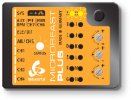
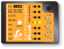
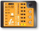
| [[File: | | [[File:MBPlus_Bank_1.png|x100px|none]] || [[File:MBPlus_Bank_2.png|x100px|none]] || [[File:MBPlus_Bank_3.png|x100px|none]] | ||
|- style="font-size: 80%;" | |- style="font-size: 80%;" | ||
| Bank 1 is indicated by LEDs AH || Bank 2 is indicated by LEDs DK || Bank 3 is indicated by LEDs GN | | Bank 1 is indicated by LEDs AH || Bank 2 is indicated by LEDs DK || Bank 3 is indicated by LEDs GN | ||
|} | |} | ||
<br /> | <br /> | ||
Following the Bank display you will see the AttitudeControl display for additional 4 seconds. When LED A flashes AttitudeControl is off, otherwise one of the Menu LEDs B - N shows the amount of AttitudeControl gain, see [[Manuals:MBPlusFblV5:AttitudeControl|AttitudeControl instructions]] for further informations.<br /> | Following the Bank display you will see the AttitudeControl display for additional 4 seconds. When LED A flashes AttitudeControl is off, otherwise one of the Menu LEDs B - N shows the amount of AttitudeControl gain, see [[Manuals:MBPlusFblV5:AttitudeControl/en|AttitudeControl instructions]] for further informations.<br /> | ||
<br /> | <br /> | ||
In order to use bank switching in flight either you can assign a 3 - position switch on your transmitter to the gyro channel (which is used for bank switching now) and select banks randomly or you can link the gyro channel with you flight mode switch, so that the parameter banks are set automatically for each flight mode.<br /> | In order to use bank switching in flight either you can assign a 3 - position switch on your transmitter to the gyro channel (which is used for bank switching now) and select banks randomly or you can link the gyro channel with you flight mode switch, so that the parameter banks are set automatically for each flight mode.<br /> | ||
<br /> | |||
<!--T:7--> | |||
'''Using a 3-Position switch to toggle parameter banks''' | |||
{|class="gallery" style="font-style: italic; font-size: x-small;" | |||
|- | |||
| width="200pt" style="padding:0px 20px;" align="center"| [[Image:Spektrum_ChannelInputConfig.png|192px|none|border]] | |||
| width="200pt" style="padding:0px 20px;" align="center"| [[Image:Spektrum_OptionChannelAssignGearSwitch.png|192px|none|border]] | |||
| width="200pt" style="padding:0px 20px;" align="center"| [[Image:Spektrum_ServoTravel_Gyro100.png|192px|none|border]] | |||
|- | |||
| width="200pt" style="padding:0px 20px; vertical-align: top;" | Assign a switch to the gyro channel... | |||
| width="200pt" style="padding:0px 20px; vertical-align: top;" | ... here we use switch G | |||
| width="200pt" style="padding:0px 20px; vertical-align: top;" | In the servo monitor you can see how the switch changes the output of gyro channel<br /><br /> | |||
|- | |||
| width="200pt" style="padding:0px 20px;" align="center"| [[Image:Spektrum_ServoTravel_Gyro0.png|192px|none|border]] | |||
| width="200pt" style="padding:0px 20px;" align="center"| [[Image:Spektrum_ServoTravel_GyroMinus100.png|192px|none|border]] | |||
| width="200pt" style="padding:0px 20px;" align="center"| [[Image:Spektrum_ServoReverseGyro.png|x100px|192px|none|border]] | |||
|- | |||
| width="200pt" style="padding:0px 20px; vertical-align: top;" | 0% (=Bank 2) | |||
| width="200pt" style="padding:0px 20px; vertical-align: top;" | -100% (=Bank 3) | |||
| width="200pt" style="padding:0px 20px; vertical-align: top;" | If you like to inverse the switch direction just reverse the gyro channel in your transmitter | |||
|}<br /> | |||
<br /> | |||
<!--T:8--> | |||
'''Using the flight mode system of your radio to automatically switch parameter banks''' | |||
{|class="gallery" style="font-style: italic; font-size: x-small;" | |||
|- | |||
| width="200pt" style="padding:0px 20px;" align="center"| [[Image:Spektrum_GyroDisabled.png|192px|none|border]] | |||
| width="200pt" style="padding:0px 20px;" align="center"| [[Image:Spektrum GyroSwitchFlightMode.png|192px|none|border]] | |||
| width="200pt" style="padding:0px 20px;" align="center"| [[Image:Spektrum_ServoTravel_Gyro100.png|x100px|192px|none|border]] | |||
|- | |||
| width="200pt" style="padding:0px 20px; vertical-align: top;" | Activate the gyro function in your transmitter... | |||
| width="200pt" style="padding:0px 20px; vertical-align: top;" | ... and use the flightmodes to control the gyro channel. Set the values to select banks for each flight mode as necessary. | |||
| width="200pt" style="padding:0px 20px; vertical-align: top;" | As already mentioned use the servo monitor and the display on the device to check whether everything is working as expected. | |||
|}<br /> | |||
<br /> | <br /> | ||
| Line 34: | Line 81: | ||
<br /> | <br /> | ||
=Setting Bank Switching with StudioX= <!--T:6--> | |||
When StudioXm has connected to your MICROBEAST PLUS in the device overview main screen click the "Parameter" button. Then click the "Next" button repeatedly until you reach the screen "Bank 1 - Gains" or directly go to this options screen using the box on top. Here you can aktivate Bank Switching clicking the specific button below the gain adjustments. When Bank switching is activated the following screens are accessible and can be used to change parameters of each of the Banks 2 & 3 besides the Paramters of Bank 1 in the beginning.<br /> | When StudioXm has connected to your MICROBEAST PLUS in the device overview main screen click the "Parameter" button. Then click the "Next" button repeatedly until you reach the screen "Bank 1 - Gains" or directly go to this options screen using the box on top. Here you can aktivate Bank Switching clicking the specific button below the gain adjustments. When Bank switching is activated the following screens are accessible and can be used to change parameters of each of the Banks 2 & 3 besides the Paramters of Bank 1 in the beginning.<br /> | ||
<br /> | <br /> | ||
Latest revision as of 13:46, 19 July 2018
Bank Switching - What's that?
With Bank Switching you can change between 3 different parameter sets in flight, instead of using only one fixed parameter set. This allows to adapt the system to different flight conditions or different rotorhead speeds, i.e. when hovering, cruising, speed flying, landing and so on. Or you can use the Bank Switching to selectively change specific parameters, i.e. switch between different rescue modes or test the effects of a parameter. Please note that due to the variety of setup options it is only possible to enable and setup the bank switching with the StudioX computer software or StudioXm App for mobile devices.
Usage instructions
When Bank Switch is activated all parameters have to be set in the software. This also includes the gains that usually are set with the 3 dials on the device as well as the tail gyro gain. There is one exception: the AttitudeControl gain can be still controlled by a separate switch channel. Only when no additional channel was assigned in RECEIVER MENU, you have to set the AttitudeGain for each Bank in the software and the selected AttitudeMode will be activated depending on the amount of gain.
The dials do not have any functionality anymore, the gyro gain channel now is used to switch between the banks. When the gyro channel is in center position Bank 2 is active, when the gyro channel is moved to positive direction Bank 1 is active, and when its moved to negative direction Bank 3 is active.
| Menu-LED (Bank) | A H (Bank 1) | D K (Bank 2) | G N (Bank 3) |
|---|---|---|---|
| Rudder channel | > +35% | -35% to +35% | < -35% |
Please note that the values may vary slightly, actually there is a little range around center position so you do not have to set the gyro channel to exactly 0% to activate bank 2. Also the signs may be interchanged depending on the type of radio system used. Anyhow, you can see in the Software/App which Bank is active at the moment as well as you can read the current bank from the display. Each time you change the Bank the Menu LEDs will light up for 4 seconds and will indicate like a little bar which Bank is selected: bar on top is Bank 1, bar in the middle is Bank 2, bar at the bottom is Bank 3.
 |
 |
 |
| Bank 1 is indicated by LEDs AH | Bank 2 is indicated by LEDs DK | Bank 3 is indicated by LEDs GN |
Following the Bank display you will see the AttitudeControl display for additional 4 seconds. When LED A flashes AttitudeControl is off, otherwise one of the Menu LEDs B - N shows the amount of AttitudeControl gain, see AttitudeControl instructions for further informations.
In order to use bank switching in flight either you can assign a 3 - position switch on your transmitter to the gyro channel (which is used for bank switching now) and select banks randomly or you can link the gyro channel with you flight mode switch, so that the parameter banks are set automatically for each flight mode.
Using a 3-Position switch to toggle parameter banks
Using the flight mode system of your radio to automatically switch parameter banks
- When using bank switching please be absolutely sure which banks you're using in flight and which are the banks you can choose from. When you do not need a bank either make sure that you can't activate it on the transmitter or copy all parameter values from another bank to this bank, so you will not switch to an unwanted condition by accident.
- When Bank Switching is disabled always the parameters of Bank 1 will be used!
- The options you can change in the devices PARAMETER MENU are always related to Bank 1, no matter whether Bank Switching is used or not!
Setting Bank Switching with StudioX
When StudioXm has connected to your MICROBEAST PLUS in the device overview main screen click the "Parameter" button. Then click the "Next" button repeatedly until you reach the screen "Bank 1 - Gains" or directly go to this options screen using the box on top. Here you can aktivate Bank Switching clicking the specific button below the gain adjustments. When Bank switching is activated the following screens are accessible and can be used to change parameters of each of the Banks 2 & 3 besides the Paramters of Bank 1 in the beginning.
Please note that the first screen "Quick trim" has global effect, meaning that the values set here are used in all of the Banks. Separate trimming for each bank is not provided.
When you've set a separate control channel for the AttitudeControl function in "Control setup" the gain adjustment for AttitudeControl in the App will have no effect. Only you can use Bank Switching then to change between different rescue modes in flight. On the other hand when you did not assign a separate channel for the AttitudeControl, you can set the AttitudeControl gain for each bank/flight mode and use the Banks/flight modes to activate/deactivate the rescue in flight. Note that AttitudeControl will enable when the gain is higher than 12! Check the status display on the device overview main screen or the display on the device to see if AttitudeControl is active and what gain is set!


