Manuals:MBUltraFblV5:TelemetryInfo: Difference between revisions
Shornstein (talk | contribs) Marked this version for translation |
Shornstein (talk | contribs) No edit summary |
||
| (3 intermediate revisions by the same user not shown) | |||
| Line 1: | Line 1: | ||
<translate> | <translate> | ||
<!--T:1--> | <!--T:1--> | ||
{{TOC_MBUltraFblV5|Manuals:MBUltraFblV5:BankSwitch/en|Manuals:MBUltraFblV5:FactoryReset/en|FEATURES|}} | {{TOC_MBUltraFblV5|Manuals:MBUltraFblV5:BankSwitch/en|Manuals:MBUltraFblV5:FactoryReset/en|FEATURES|}} | ||
| Line 14: | Line 15: | ||
= SPEKTRUM SRXL2 = <!--T:4--> | = SPEKTRUM SRXL2 = <!--T:4--> | ||
Make sure you receiver is bound as telemetry receiver. Usually this happens automatically when binding the receiver. Message on the radio during bind procedure: "DMSX 11ms - Telemetry".<br /> | |||
<br /> | |||
To enable telemetry display on your SPEKTRUM radio, open the "Function List" and choose telemetry options screen. Here enable "Volts", "ESC", "RPM" and "Flight pack" displays. You don't have to enable all screens, but basically this is what is used by MICROBEAST. If you enter one of the screens, you can enable the specific alarms for each metric, i. e. enable a low voltage alarm from the "Volts" setting, or add maximum allowed capacity draw from the "Flight pack" screen. Please refer to the manual of you SPEKTRUM radio for more information.<br /> | |||
<br /> | <br /> | ||
{| cellspacing="20" | |||
|- style="text-align: center;" | |||
| [[File:Spektrum_Telemetry_fucntionlist.png|x120px]] | |||
| [[File:Spektrum_Telemetry_overview.png|x120px]] | |||
| [[File:Spektrum Telemetry voltage.png|x120px]] | |||
|}<br /> | |||
<br /> | |||
From the main screen you can then scroll through the different telemetry screens: | |||
{| cellspacing="20" | |||
|- style="text-align: center;" | |||
|[[File:Spektrum Telemetry voltagestatus.png|x120px]] | |||
| [[File:Spektrum Telemetry escstatus.png|x120px]] | |||
| [[File:Spektrum Telemetry fpackstatus.png|x120px]] | |||
|}<br /> | |||
<br /> | |||
= GRAUPNER HOTT = <!--T:5--> | = GRAUPNER HOTT = <!--T:5--> | ||
| Line 40: | Line 60: | ||
<br /> | <br /> | ||
= FRSky F. | = FRSky F.Port = <!--T:6--> | ||
Make sure you receiver is set up to send data in F. | Make sure you receiver is set up to send data in "F.Port" data format. Usually this is done from the MODEL MENU of your FRSky radio.<br /> | ||
<br /> | <br /> | ||
If telemetry data is received, you should see all available data when starting the SCAN PROCESS in TELEMETRY MENU of your FRSky radio.<br /> | If telemetry data is received, you should see all available data when starting the SCAN PROCESS in TELEMETRY MENU of your FRSky radio.<br /> | ||
| Line 65: | Line 85: | ||
* SLOT 12: TEMP-1713 (=ESC temperature) | * SLOT 12: TEMP-1713 (=ESC temperature) | ||
* SLOT 13: TEMP-1713 (=PWM) | * SLOT 13: TEMP-1713 (=PWM) | ||
{| cellspacing="20" | |||
|- style="text-align: center;" | |||
| [[File:SBUS2 (2).jpg|x150px]] | |||
| [[File:SBUS2 (1).jpg|x150px]] | |||
|} | |||
<br /> | <br /> | ||
Please note this assignment is fixed. If you use additional sensors on the same slots, these must be reassigned to other slots.<br /> | Please note this assignment is fixed. If you use additional sensors on the same slots, these must be reassigned to other slots.<br /> | ||
Latest revision as of 09:34, 19 December 2023
For telemetry usage you need to setup your radio system. Here we describe basic steps how to enable the telemetry display on different radio systems. For further information on setting up alarms and other options, please refer to the instruction manual of the radio system.
JETI EXBUS
SPEKTRUM SRXL2
Make sure you receiver is bound as telemetry receiver. Usually this happens automatically when binding the receiver. Message on the radio during bind procedure: "DMSX 11ms - Telemetry".
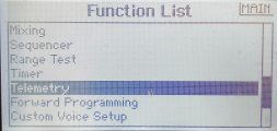
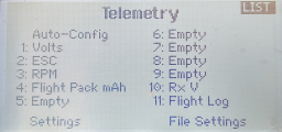
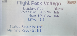
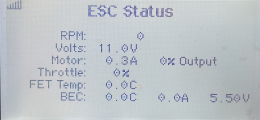
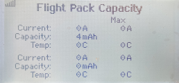
To enable telemetry display on your SPEKTRUM radio, open the "Function List" and choose telemetry options screen. Here enable "Volts", "ESC", "RPM" and "Flight pack" displays. You don't have to enable all screens, but basically this is what is used by MICROBEAST. If you enter one of the screens, you can enable the specific alarms for each metric, i. e. enable a low voltage alarm from the "Volts" setting, or add maximum allowed capacity draw from the "Flight pack" screen. Please refer to the manual of you SPEKTRUM radio for more information.
|
|
|
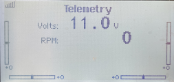
From the main screen you can then scroll through the different telemetry screens:
|
|
|
GRAUPNER HOTT
Make sure you receiver is set up to send telemetry data on the external telemetry data output. Usually this is done from the TELEMETRY MENU of your HOTT radio.
The telemetry data line is connected to [SYS] port of MICROBEAST ULTRA. For this type of application you must set RECEIVER MENU point L to Status LED blue (="HOTT").
See section "Telemetry" in RECEIVER MENU for additional information.
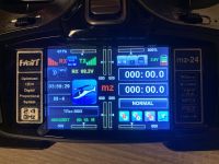
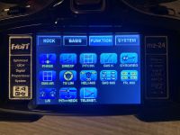
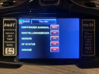
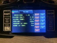
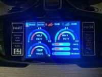
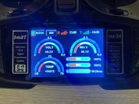
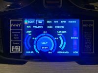
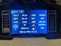
To get telemetry information on your radio's display, there is not much to do. Just make sure to switch on the radio and receiver simultaneously. If you open the TELEMETRY tab on the radio you should see the "SEARCH" label, indicating that telemetry data received by the radio. After apprx. 15 seconds, the radio should display telemetry data. MICROBEAST ULTRA is simulating a HOTT EAM (Electric Air Module) and VARIO. So you will see the associated screens on the radio.
|
|
|
|
|
|
|
|
FRSky F.Port
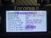
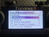
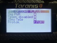
Make sure you receiver is set up to send data in "F.Port" data format. Usually this is done from the MODEL MENU of your FRSky radio.
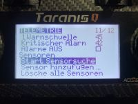
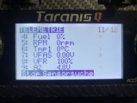
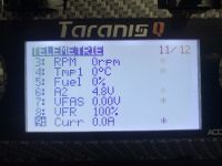
If telemetry data is received, you should see all available data when starting the SCAN PROCESS in TELEMETRY MENU of your FRSky radio.
|
|
|
|
|
|
Futaba SBUS2
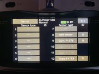
Make sure you receiver is set up to send SBUS2 telemetry data. Usually this is done from the LINKAGE MENU of your Futaba radio. Sometimes it is necessary to perform a rebind, in order to activate the telemetry output!
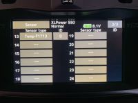
In the SENSOR menu activate the following devices:
- SLOT 8: rpm sensor (=headspeed)
- SLOTs 9-10-11: CUR-1678 (=voltage, current, consumption)
- SLOT 12: TEMP-1713 (=ESC temperature)
- SLOT 13: TEMP-1713 (=PWM)
|
|
Please note this assignment is fixed. If you use additional sensors on the same slots, these must be reassigned to other slots.
You can add alarms to each item in the TELEMETRY menu. Please refer to the instructions manual of your radio for further reference.