MBPlus AttitudeControl-HowToSetupTX: Difference between revisions
Shornstein (talk | contribs) No edit summary |
Shornstein (talk | contribs) No edit summary |
||
| (5 intermediate revisions by the same user not shown) | |||
| Line 2: | Line 2: | ||
<br /> | <br /> | ||
<translate> | <translate> | ||
{{DISPLAYTITLE: How to setup transmitter and perform function assignment|noerror}} | |||
===Setting up a separate switch channel for AttitudeControl=== <!--T:8--> | ===Setting up a separate switch channel for AttitudeControl=== <!--T:8--> | ||
In this example we use a Futaba T14SG with R7008SB SBus receiver. The procedure is basically the same on all types of transmitter systems. For this type of application it is mandatory to use a system with singleline receiver output like SBus, SRXL, SPPM or Spektrum remote satellite signal.<br /> | In this example we use a Futaba T14SG with R7008SB SBus receiver. The procedure is basically the same on all types of transmitter systems. For this type of application it is mandatory to use a system with singleline receiver output like SBus, SRXL, SPPM or Spektrum remote satellite signal.<br /> | ||
| Line 10: | Line 11: | ||
|- | |- | ||
|width="400pt" style="padding:0px 20px;" align="center"|[[Image:Futaba Channels.jpg|192px|none|border]] | |width="400pt" style="padding:0px 20px;" align="center"|[[Image:Futaba Channels.jpg|192px|none|border]] | ||
|width=" | |width="400pt" style="padding:0px 20px; vertical-align: bottom;" align="center"|[[Image:Futabasetup_1.JPG|192px|none|border]] | ||
|width="400pt" style="padding:0px 20px;" align="center"|[[Image:Futabasetup_2.JPG|192px|none|border]] | |width="400pt" style="padding:0px 20px; vertical-align: bottom;" align="center"|[[Image:Futabasetup_2.JPG|192px|none|border]] | ||
|- | |- | ||
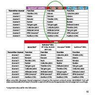
|width="200pt" style="padding:0px 20px;"|We use the default channel ordering here. Make sure that the functions of your transmitter are assigned to the same output channels as written in the MICROBEAST PLUS manual. | |width="200pt" style="padding:0px 20px; vertical-align: top;"|We use the default channel ordering here. Make sure that the functions of your transmitter are assigned to the same output channels as written in the MICROBEAST PLUS manual. | ||
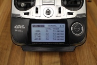
|width="200pt" style="padding:0px 20px;"|On the Futaba transmitter we use the FUNCTION menu to check and assign functions. | |width="200pt" style="padding:0px 20px; vertical-align: top;"|On the Futaba transmitter we use the FUNCTION menu to check and assign functions. | ||
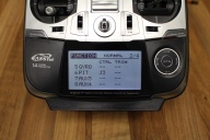
|width="200pt" style="padding:0px 20px;"|As channel 7 is used to switch AttitudeControl we must assign some actuator to this channel. On the Futaba transmitter the channel is designated as AUX channel which means this is a simple proportional channel without any special functionality. | |width="200pt" style="padding:0px 20px; vertical-align: top;"|As channel 7 is used to switch AttitudeControl we must assign some actuator to this channel. On the Futaba transmitter the channel is designated as AUX channel which means this is a simple proportional channel without any special functionality. | ||
|} | |} | ||
<br /> | <br /> | ||
| Line 21: | Line 22: | ||
|- | |- | ||
|width="400pt" style="padding:0px 20px;" align="center"|[[Image:Futabasetup_3.JPG|192px|none|border]] | |width="400pt" style="padding:0px 20px;" align="center"|[[Image:Futabasetup_3.JPG|192px|none|border]] | ||
|width=" | |width="400pt" style="padding:0px 20px;" align="center"|[[Image:Futabasetup_4.JPG|192px|none|border]] | ||
|width="400pt" style="padding:0px 20px;" align="center"|[[Image:Futabasetup_5.JPG|192px|none|border]] | |width="400pt" style="padding:0px 20px;" align="center"|[[Image:Futabasetup_5.JPG|192px|none|border]] | ||
|- | |- | ||
| Line 34: | Line 35: | ||
|- | |- | ||
|width="400pt" style="padding:0px 20px;" align="center"|[[Image:Futabasetup_65.JPG|192px|none|border]] | |width="400pt" style="padding:0px 20px;" align="center"|[[Image:Futabasetup_65.JPG|192px|none|border]] | ||
|width=" | |width="300pt" style="padding:0px 20px;" align="center"|[[Image:IMG 3205.JPG|192px|none|border]] | ||
|width=" | |width="300pt" style="padding:0px 20px;" align="center"|[[Image:IMG 3206.JPG|192px|none|border]] | ||
|width="200pt" style="padding:0px 20px;"|[[Image:IMG 3209.JPG|192px|none|border]] | |width="200pt" style="padding:0px 20px;" align="center"|[[Image:IMG 3209.JPG|192px|none|border]] | ||
|- | |- | ||
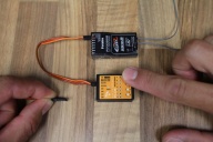
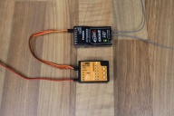
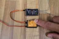
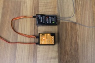
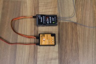
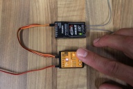
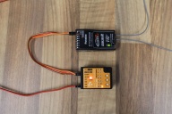
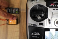
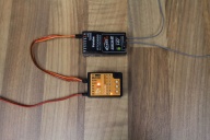
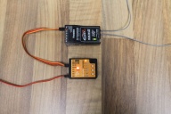
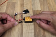
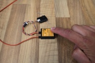
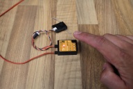
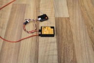
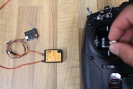
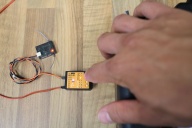
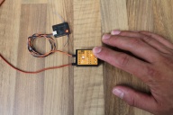
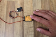
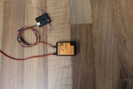
|width="200pt" style="padding:0px 20px; vertical-align: top;"|The serial signal line is connected to ELE/DI1 input at MICROBEAST PLUS. For setup the power supply can be connected to one of the servo output port CH1 to CH4. Before and while switching on/connecting power we hold down the push button to enter receiver setup menu. | |width="200pt" style="padding:0px 20px; vertical-align: top;"|The serial signal line is connected to ELE/DI1 input at MICROBEAST PLUS. For setup the power supply can be connected to one of the servo output port CH1 to CH4. Before and while switching on/connecting power we hold down the push button to enter receiver setup menu. | ||
| Line 46: | Line 47: | ||
|- | |- | ||
|width="400pt" style="padding:0px 20px;" align="center"|[[Image:IMG 3210.JPG|192px|none|border]] | |width="400pt" style="padding:0px 20px;" align="center"|[[Image:IMG 3210.JPG|192px|none|border]] | ||
|width=" | |width="300pt" style="padding:0px 20px;" align="center"|[[Image:IMG 3213.JPG|192px|none|border]] | ||
|width=" | |width="300pt" style="padding:0px 20px;" align="center"|[[Image:IMG 3215.JPG|192px|none|border]] | ||
|width="200pt" style="padding:0px 20px;"|[[Image:IMG 3217.JPG|192px|none|border]] | |width="200pt" style="padding:0px 20px;" align="center"|[[Image:IMG 3217.JPG|192px|none|border]] | ||
|- | |- | ||
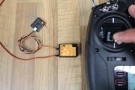
|width="200pt" style="padding:0px 20px; vertical-align: top;"|Briefly push the button to proceed to function assignment (Menu point B) where the Status LED should light up in blue color if the transmitter is on and the SBus signal is received. | |width="200pt" style="padding:0px 20px; vertical-align: top;"|Briefly push the button to proceed to function assignment (Menu point B) where the Status LED should light up in blue color if the transmitter is on and the SBus signal is received. | ||
| Line 61: | Line 62: | ||
{|class="gallery" style="font-style: italic" | {|class="gallery" style="font-style: italic" | ||
|- | |- | ||
|width=" | |width="400pt" style="padding:0px 20px;" align="center"|[[Image:IMG 3222.JPG|192px|none|border]] | ||
|width="300pt" style="padding:0px 20px;" align="center"|[[Image:IMG 3219.JPG|192px|none|border]] | |width="300pt" style="padding:0px 20px;" align="center"|[[Image:IMG 3219.JPG|192px|none|border]] | ||
|width="300pt" style="padding:0px 20px;" align="center"|[[Image:IMG 3228.JPG|192px|none|border]] | |width="300pt" style="padding:0px 20px;" align="center"|[[Image:IMG 3228.JPG|192px|none|border]] | ||
|width="200pt" style="padding:0px 20px;"|[[Image:IMG 3226.JPG|192px|none|border]] | |width="200pt" style="padding:0px 20px;" align="center"|[[Image:IMG 3226.JPG|192px|none|border]] | ||
|- | |- | ||
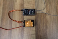
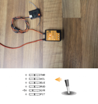
|width="200pt" style="padding:0px 20px; vertical-align: top;"|Flipping the switch into one direction AttitudeControl is on. This is shown by Menu LED N lighting up while the Status LED is red. | |width="200pt" style="padding:0px 20px; vertical-align: top;"|Flipping the switch into one direction AttitudeControl is on. This is shown by Menu LED N lighting up while the Status LED is red. | ||
| Line 79: | Line 80: | ||
{|class="gallery" style="font-style: italic" | {|class="gallery" style="font-style: italic" | ||
|- | |- | ||
|width=" | |width="300pt" style="padding:0px 20px;" align="center"|[[Image:Gyro switch.png|192px|none|border]] | ||
|width="300pt" style="padding:0px 20px;" align="center"|[[Image:Gyro 50.png|192px|none|border]] | |width="300pt" style="padding:0px 20px;" align="center"|[[Image:Gyro 50.png|192px|none|border]] | ||
|width=" | |width="400pt" style="padding:0px 20px;" align="center"|[[Image:Attctrl 50.png|192px|none|border]] | ||
|width=" | |width="200pt" style="padding:0px 20px;" align="center"|[[Image:Gyro_onoff.png|192px|none|border]] | ||
|- | |- | ||
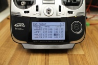
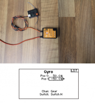
|width="200pt" style="padding:0px 20px; vertical-align: top;"|In the transmitter's gyro menu we assign a switch to control the gyro channel (channel 5). | |width="200pt" style="padding:0px 20px; vertical-align: top;"|In the transmitter's gyro menu we assign a switch to control the gyro channel (channel 5). | ||
| Line 94: | Line 95: | ||
|- | |- | ||
|width="300pt" style="padding:0px 20px;" align="center"|[[Image:Lock thr.png|192px|none|border]] | |width="300pt" style="padding:0px 20px;" align="center"|[[Image:Lock thr.png|192px|none|border]] | ||
|width=" | |width="300pt" style="padding:0px 20px;" align="center"|[[Image:SPM_0020.png|192px|none|border]] | ||
|width=" | |width="400pt" style="padding:0px 20px;" align="center"|[[Image:Thr_locked.png|192px|none|border]] | ||
|width=" | |width="200pt" style="padding:0px 20px;" align="center"|[[Image:Other_functions.png|192px|none|border]] | ||
|- | |- | ||
|width="200pt" style="padding:0px 20px; vertical-align: top;"|For manual function assignment we need to be able to lock the throttle output when moving the thrust stick. | |width="200pt" style="padding:0px 20px; vertical-align: top;"|For manual function assignment we need to be able to lock the throttle output when moving the thrust stick. | ||
| Line 109: | Line 110: | ||
|- | |- | ||
|width="400pt" style="padding:0px 20px;" align="center"|[[Image:SpektrumSetup 1.jpg|192px|none|border]] | |width="400pt" style="padding:0px 20px;" align="center"|[[Image:SpektrumSetup 1.jpg|192px|none|border]] | ||
|width=" | |width="300pt" style="padding:0px 20px;" align="center"|[[Image:SpektrumSetup 2.jpg|192px|none|border]] | ||
|width="200pt" style="padding:0px 20px;"|[[Image:SpektrumSetup 3.jpg|192px|none|border]] | |width="200pt" style="padding:0px 20px;" align="center"|[[Image:SpektrumSetup 3.jpg|192px|none|border]] | ||
|width=" | |width="300pt" style="padding:0px 20px;" align="center"|[[Image:SpektrumSetup 4.jpg|192px|none|border]] | ||
|- | |- | ||
|width="200pt" style="padding:0px 20px; vertical-align: top;"|The serial signal line is connected to ELE/DI1 input at MICROBEAST PLUS. For setup the power supply can be connected to one of the servo output port CH1 to CH4. Before and while switching on/connecting power we hold down the push button to enter receiver setup menu. | |width="200pt" style="padding:0px 20px; vertical-align: top;"|The serial signal line is connected to ELE/DI1 input at MICROBEAST PLUS. For setup the power supply can be connected to one of the servo output port CH1 to CH4. Before and while switching on/connecting power we hold down the push button to enter receiver setup menu. | ||
| Line 121: | Line 122: | ||
|- | |- | ||
|width="400pt" style="padding:0px 20px;" align="center"|[[Image:SpektrumSetup 5.jpg|192px|none|border]] | |width="400pt" style="padding:0px 20px;" align="center"|[[Image:SpektrumSetup 5.jpg|192px|none|border]] | ||
|width=" | |width="300pt" style="padding:0px 20px;" align="center"|[[Image:SpektrumSetup 6.jpg|192px|none|border]] | ||
|width="200pt" style="padding:0px 20px;"|[[Image:SpektrumSetup 7.jpg|192px|none|border]] | |width="200pt" style="padding:0px 20px;" align="center"|[[Image:SpektrumSetup 7.jpg|192px|none|border]] | ||
|width=" | |width="300pt" style="padding:0px 20px;" align="center"|[[Image:SpektrumSetup 8.jpg|192px|none|border]] | ||
|- | |- | ||
|width="200pt" style="padding:0px 20px; vertical-align: top;"|Briefly push the button to proceed to function assignment (Menu point B) where the Status LED should light up in blue color if the transmitter is on and the Spektrum remote signal is received. | |width="200pt" style="padding:0px 20px; vertical-align: top;"|Briefly push the button to proceed to function assignment (Menu point B) where the Status LED should light up in blue color if the transmitter is on and the Spektrum remote signal is received. | ||
| Line 133: | Line 134: | ||
|- | |- | ||
|width="200pt" style="padding:0px 20px;" align="center"|[[Image:SpektrumSetup 9.jpg|192px|none|border]] | |width="200pt" style="padding:0px 20px;" align="center"|[[Image:SpektrumSetup 9.jpg|192px|none|border]] | ||
|width=" | |width="400pt" style="padding:0px 20px;" align="center"|[[Image:SpektrumSetup 10.jpg|192px|none|border]] | ||
|width="200pt" style="padding:0px 20px;"|[[Image:SpektrumSetup 11.jpg|192px|none|border]] | |width="200pt" style="padding:0px 20px;" align="center"|[[Image:SpektrumSetup 11.jpg|192px|none|border]] | ||
|width="400pt" style="padding:0px 20px;"|[[Image:SpektrumSetup 12.jpg|192px|none|border]] | |width="400pt" style="padding:0px 20px;" align="center"|[[Image:SpektrumSetup 12.jpg|192px|none|border]] | ||
|- | |- | ||
|width="200pt" style="padding:0px 20px; vertical-align: top;"|At menu point G release the throttle hold switch to unlock the throttle control and teach the throttle channel again by moving the thrust stick. | |width="200pt" style="padding:0px 20px; vertical-align: top;"|At menu point G release the throttle hold switch to unlock the throttle control and teach the throttle channel again by moving the thrust stick. | ||
| Line 145: | Line 146: | ||
|- | |- | ||
|width="200pt" style="padding:0px 20px;" align="center"|[[Image:SpektrumSetup 13.jpg|192px|none|border]] | |width="200pt" style="padding:0px 20px;" align="center"|[[Image:SpektrumSetup 13.jpg|192px|none|border]] | ||
|width="400pt" style="padding:0px 20px;"|[[Image:SpektrumSetup 14.jpg|192px|none|border]] | |width="400pt" style="padding:0px 20px;" align="center"|[[Image:SpektrumSetup 14.jpg|192px|none|border]] | ||
|width=" | |width="200pt" style="padding:0px 20px;" align="center"|[[Image:SpektrumSetup 15.jpg|192px|none|border]] | ||
|- | |- | ||
|width="200pt" style="padding:0px 20px; vertical-align: top;"|Last step is menu point N. | |width="200pt" style="padding:0px 20px; vertical-align: top;"|Last step is menu point N. | ||
| Line 159: | Line 160: | ||
{|class="gallery" style="font-style: italic" | {|class="gallery" style="font-style: italic" | ||
|- | |- | ||
|width=" | |width="400pt" style="padding:0px 20px;" align="center"|[[Image:Att SetupGyro 1.png|192px|none|border]] | ||
|width=" | |width="400pt" style="padding:0px 20px;" align="center"|[[Image:Att SetupGyro 2.png|192px|none|border]] | ||
|width=" | |width="400pt" style="padding:0px 20px;" align="center"|[[Image:Att SetupGyro 3.png|192px|none|border]] | ||
|- | |- | ||
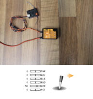
|width="200pt" style="padding:0px 20px; vertical-align: top;"|Flipping the switch into one direction AttitudeControl is ON. This is shown by Menu LED G lighting up while the Status LED is red. By adjusting the servo throw of the gyro channel into this direction you can adjust the AttitudeControl gain later. | |width="200pt" style="padding:0px 20px; vertical-align: top;"|Flipping the switch into one direction AttitudeControl is ON. This is shown by Menu LED G lighting up while the Status LED is red. By adjusting the servo throw of the gyro channel into this direction you can adjust the AttitudeControl gain later. | ||
Latest revision as of 11:02, 21 March 2016
Setting up a separate switch channel for AttitudeControl
In this example we use a Futaba T14SG with R7008SB SBus receiver. The procedure is basically the same on all types of transmitter systems. For this type of application it is mandatory to use a system with singleline receiver output like SBus, SRXL, SPPM or Spektrum remote satellite signal.
Using a Standard type receiver assigning channels and using a separate switch channel for AtittudeControl is NOT applicable as here you can only connect 5 channels to Microbeast and the channel assignment is fixed to the receiver output wires!
 |
 |
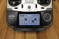 |
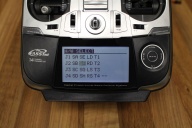
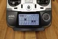
| We choose switch SF to actuate the channel 7. | In the servo monitor we can see how the deflection of channel 7 is changing... | ...when we flip switch SF |
After the basic transmitter setup is done we have to choose the receiver type and assign the functions by choosing the default channel assignment for our SBus system. Before doing so make sure the receiver is properly bound to the transmitter and the receiver is sending a serial line signal on the appropriate output (in our case we have to setup the receiver so it is sending a SBus signal on the output 8/SB by setting the receiver to "Mode B", see receiver manual).
Note you must go through the complete receiver setup menu until you reach the menu end (all Menu LEDs flashing). Otherwise your settings will not be stored.
Now power off and on again. MICROBEAST PLUS will perform initialization sequence. When the init is finished perform basic setup procedure (if not already done). When the heli is ready to fly open Parameter menu by briefly pushing the button while in operation mode and directly go to menu point L by skipping the other menu points pushing the button repeatedly. At menu point L choose your desired AttitudeControl mode and save it by again pushing the button briefly. If using a AttitudeControl mode with collective pitch input you may change the pitch at menu point M. When out of the Parameter menu check if AttitudeControl reacts correctly when flipping your AttitudeControl switch.
Don't forget: AttitudeControl gain and status will only be shown each time after the gain changes which is the case when flipping the switch. After 8 seconds the Menu LED will go off and the Status LED color changes back to blue or purple showing the tail gyro mode.
Setting up AttitudeControl using the gyro gain channel
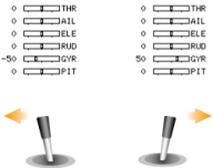
Especially when using a transmitter with 6 channels only or when using a receiver with "Standard" 5-wire layout the channel for adjusting tail gyro gain (channel 5) can also be used to activate/deactivate AttitudeControl. Here instead of toggling the tail gyro between "Normal-Rate" and "HeadingLock" mode you activate the AttitudeControl when changing the direction of gyro channel. The tail gyro can only be operated in "HeadingLock" mode. When adjusting the throw in the direction where AttitudeControl is OFF, this will change the tail gyro gain. When adjusting the servo throw of the gain channel in the direction where AttitudeControl is ON, this will change the gain of AttitudeControl.
To setup MICROBEAST PLUS for this kind of operation you must perform the function assignment in receiver setup menu manually as by default it is intended that a separate channel is used for AttitudeControl.
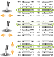
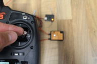
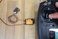
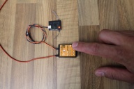
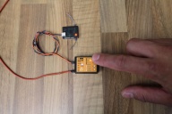
In Receiver setup menu we choose the correct receiver type (in this example we use a Spektrum remote satellite in combination with a Spektrum DX6 transmitter) and assign the transmitter channels to the functions by moving the appropriate control sticks on the transmitter.
Note you must go through the complete receiver setup menu until you reach the menu end (all Menu LEDs flashing). Otherwise your settings will not be stored.
Power off and on again. MICROBEAST PLUS will perform initialization sequence. When the init is finished perform basic setup procedure (if not already done). When the heli is ready to fly open Parameter menu by briefly pushing the button while in operation mode and directly go to menu point L by skipping the other menu points pushing the button repeatedly. At menu point L choose your desired AttitudeControl mode and save it by again pushing the button briefly. If using a AttitudeControl mode with collective pitch input you may change the pitch at menu point M. When out of the Parameter menu check if AttitudeControl reacts correctly when flipping your AttitudeControl switch.
Don't forget: AttitudeControl gain and status will only be shown each time after the gain changes which is the case when flipping the switch. After 8 seconds the Menu LED will go off and the Status LED color changes back to blue showing the tail gyro mode.
