Manuals:MBPlusFblV5:Setupmenu H: Difference between revisions
Shornstein (talk | contribs) Created page with "<translate> {{DISPLAYTITLE:SETUP MENU H - Servo trim|noerror}} {{TOC_MBPlusV5}} __TOC__ <br /> At SETUP MENU point H we trim the servo center positions so that each servo hor..." |
Shornstein (talk | contribs) No edit summary |
||
| Line 5: | Line 5: | ||
<br /> | <br /> | ||
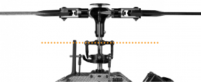
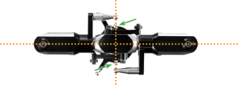
At SETUP MENU point H we trim the servo center positions so that each servo horn forms an exact 90 degrees angle with the adjustment linkage. This is necessary as usually you will not be able to attach the servo horns in exact center position to the servo. '''After all servos have been trimmed do not proceed to the next menu point yet.''' With active trimming adjust the linkage rods according to your helicopter manual. The swashplate should now be at the midpoint and perpendicular to the main shaft and the rotor blades should have 0 degrees of pitch. Always work this out from bottom (servos) to top (blade grips). Also don‘t forget to level and phase the swashplate driver in the correct way (if it‘s adjustable)! At 0 degrees of pitch the swash driver arms must be horizontal and the linkage balls of the blade grips have to be perpendicular to the spindle shaft.<br /> | At SETUP MENU point H we trim the servo center positions so that each servo horn forms an exact 90 degrees angle with the adjustment linkage. This is necessary as usually you will not be able to attach the servo horns in exact center position to the servo. '''After all servos have been trimmed do not proceed to the next menu point yet.''' With active trimming adjust the linkage rods according to your helicopter's manual. The swashplate should now be at the midpoint and perpendicular to the main shaft and the rotor blades should have 0 degrees of pitch. Always work this out from bottom (servos) to top (blade grips). Also don‘t forget to level and phase the swashplate driver in the correct way (if it‘s adjustable)! At 0 degrees of pitch the swash driver arms must be horizontal and the linkage balls of the blade grips have to be perpendicular to the spindle shaft.<br /> | ||
<br /> | <br /> | ||
[[Image:Swashdriver_1.png| | {| | ||
|- | |||
[[Image:Swashdriver_2.png| | | [[Image:Swashdriver_1.png|x120px|border]] | ||
| [[Image:Swashdriver_2.png|x120px|border]] | |||
|}<br /> | |||
<br /> | <br /> | ||
<br /> | <br /> | ||
| Line 18: | Line 20: | ||
By tapping the aileron stick you can select one servo after another. Every color of the Status-LED is corresponding to a specific servo channel that is indicating its selection by a short up and down move. Use the rudder stick to change the servo trimming/adjust the center position. You can switch back and forth between the servos as often as you need.<br /> | By tapping the aileron stick you can select one servo after another. Every color of the Status-LED is corresponding to a specific servo channel that is indicating its selection by a short up and down move. Use the rudder stick to change the servo trimming/adjust the center position. You can switch back and forth between the servos as often as you need.<br /> | ||
<br /> | <br /> | ||
{ | {|cellpadding="4" cellspacing="0" border="1" | ||
|CH 1 – elevator servo | | style="width:100px; text-align:left;" | '''Status-LED''' || style="text-align:center;" | '''Servo trim''' | ||
|CH 2 – aileron(1) servo | |- | ||
|CH 3 – aileron(2) / pitch servo (mCCPM) | |style="color:white; background-color:black" | off || all zero | ||
|CH 7 – elevator servo(2) (90° eCCPM only) | |- | ||
} | | style="color:white; background-color:#CC66CC" | purple || CH 1 – elevator servo | ||
|- | |||
|style="color:white; background-color:#FF3300" | red ||CH 2 – aileron(1) servo | |||
|- | |||
| style="color:white; background-color:#0066FF" | blue || CH 3 – aileron(2) / pitch servo (mCCPM) | |||
|- | |||
| style="color:white; background: linear-gradient(to right, #FF3300, black, #0066FF)" | red/blue || CH 7 – elevator servo(2) (90° eCCPM only) | |||
|}<br /> | |||
<br /> | |||
<br /> | <br /> | ||
| Line 29: | Line 39: | ||
To activate the servo trim adjustments click the '''Adjust button''' in the corresponding table row (when using the '''Wizard''' function this will be done automatically when you click the '''Next button''' after adjusting Menu Point G). For your reference the servos will briefly move up and down once one after another in the given order CH1 to CH3 (CH7) so you can identify them easily. Trim each servo so that the servo horn forms an exact 90 degrees angle with the linkage rod. Then make the mechanical adjustment for the linkages as described above if necessary. Finally click the '''Save button''' or '''Next button''' (when using the '''Wizard''' function) to finish the servo trim adjustment.<br /> | To activate the servo trim adjustments click the '''Adjust button''' in the corresponding table row (when using the '''Wizard''' function this will be done automatically when you click the '''Next button''' after adjusting Menu Point G). For your reference the servos will briefly move up and down once one after another in the given order CH1 to CH3 (CH7) so you can identify them easily. Trim each servo so that the servo horn forms an exact 90 degrees angle with the linkage rod. Then make the mechanical adjustment for the linkages as described above if necessary. Finally click the '''Save button''' or '''Next button''' (when using the '''Wizard''' function) to finish the servo trim adjustment.<br /> | ||
<br /> | <br /> | ||
[[File:SetupH. | [[File:SetupH.PNG|x250px]]<br /> | ||
<br /> | <br /> | ||
<br /> | <br /> | ||
Revision as of 12:30, 30 November 2017
At SETUP MENU point H we trim the servo center positions so that each servo horn forms an exact 90 degrees angle with the adjustment linkage. This is necessary as usually you will not be able to attach the servo horns in exact center position to the servo. After all servos have been trimmed do not proceed to the next menu point yet. With active trimming adjust the linkage rods according to your helicopter's manual. The swashplate should now be at the midpoint and perpendicular to the main shaft and the rotor blades should have 0 degrees of pitch. Always work this out from bottom (servos) to top (blade grips). Also don‘t forget to level and phase the swashplate driver in the correct way (if it‘s adjustable)! At 0 degrees of pitch the swash driver arms must be horizontal and the linkage balls of the blade grips have to be perpendicular to the spindle shaft.

|

|
Adjustment on the device
Initially when the trimming is 0 on all servos the Status LED will be off. Attach the servo horns on the servos at their true center position, so that you get roughly equal throws to both direction. Mount the servo horns so that they form as much as possible a 90 degrees angle to the linkage rod. Then in the next step you electronically fine trim every single servo‘s center position, as usually mounting the servo horn at exact 90 degrees will not work out perfectly depending on the servo‘s gear train and the servo horn.
By tapping the aileron stick you can select one servo after another. Every color of the Status-LED is corresponding to a specific servo channel that is indicating its selection by a short up and down move. Use the rudder stick to change the servo trimming/adjust the center position. You can switch back and forth between the servos as often as you need.
| Status-LED | Servo trim |
| off | all zero |
| purple | CH 1 – elevator servo |
| red | CH 2 – aileron(1) servo |
| blue | CH 3 – aileron(2) / pitch servo (mCCPM) |
| red/blue | CH 7 – elevator servo(2) (90° eCCPM only) |
Setup with StudioX
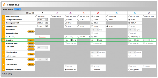
To activate the servo trim adjustments click the Adjust button in the corresponding table row (when using the Wizard function this will be done automatically when you click the Next button after adjusting Menu Point G). For your reference the servos will briefly move up and down once one after another in the given order CH1 to CH3 (CH7) so you can identify them easily. Trim each servo so that the servo horn forms an exact 90 degrees angle with the linkage rod. Then make the mechanical adjustment for the linkages as described above if necessary. Finally click the Save button or Next button (when using the Wizard function) to finish the servo trim adjustment.
Setup with StudioXm
When the servo trim screen appears, for your reference the servos will briefly move up and down once one after another in the given order CH1 to CH3 (CH7) so you can identify them easily. Trim each servo using the + and - buttons so that the servo horn forms an exact 90 degrees angle with the linkage rod. Then make the mechanical adjustment for the linkages as described above if necessary. Finally click the Save button or Next button (when using the Wizard function) to finish the servo trim adjustment.
File:SetupHm.png
