Translations:Manuals:MB Plus:Receiver setup menu B/2/en: Difference between revisions

From BEASTX Wiki
Jump to navigation Jump to search
FuzzyBot (talk | contribs)
Importing a new version from external source
FuzzyBot (talk | contribs)
Importing a new version from external source
Line 1: Line 1:
===Preset channel assignment===
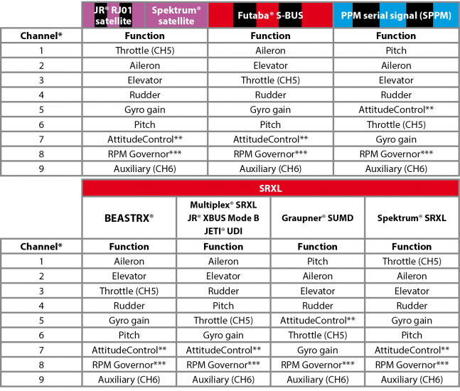
<p>For each specific type of single-line receiver selected at [[Manuals:MB_Plus:Receiver_setup_menu_A|menu point '''A''']] there is an appropriate type of receiver channel allocation saved in MICROBEAST PLUS. Please refer to the tables below. Use the column that represents your receiver type and the Status-LED color that was set at [[Manuals:MB_Plus:Receiver_setup_menu_A|menu point '''A''']] and check if your radio transmits the channels in the defined order respectively each stick function on the radio is transmitted using the specified channel number on the left. To know the channel assignment of your transmitter you can check the user manual of the transmitter or look at the servo monitor of the transmitter if it has this feature. If in doubt ask the manufacturer of your transmitter.</p>
<p>&nbsp;</p>
{{NL}}
<p>
<!--
{|cellspacing="0" cellpadding="2" border="1" style="text-align:center;border:0px solid; padding:0px"
!colspan="2" style="color:white; background-color:white; border:0px solid"|
Line 34: Line 34:
|-style="font-size: 13px; text-align:center;"
|-style="font-size: 13px; text-align:center;"
| '''9''' || CH6 Output || CH6 Output || CH6 Output || CH6 Output || CH6 Output || CH6 Output || CH6 Output
| '''9''' || CH6 Output || CH6 Output || CH6 Output || CH6 Output || CH6 Output || CH6 Output || CH6 Output
|}</p>
|} -->
<p>&nbsp;</p>
[[File:Function_assignment_EN.png|none|x550px]]
<p>
<p>
<span style="font-size: 13px;">&#42;Channel designation of Spektrum® transmitters:</span>
:<span style="font-size: small;">&#42;Channel designation of Spektrum® transmitters:</span>
{|cellpadding="2" cellspacing="0" border="1" style="font-size: 12px; text-align:center;"
:{|cellpadding="2" cellspacing="0" border="1" style="font-size: x-small; text-align:center;"
| style="width:80px;" | '''1''' || style="width:80px;" | '''2''' || style="width:80px;" | '''3''' || style="width:80px;" | '''4''' || style="width:80px;" | '''5''' || style="width:80px;" | '''6''' || style="width:80px;" | '''7''' || style="width:80px;" | '''8''' || style="width:80px;" | '''9'''
| style="width:65px;" | '''1''' || style="width:65px;" | '''2''' || style="width:65px;" | '''3''' || style="width:65px;" | '''4''' || style="width:65px;" | '''5''' || style="width:65px;" | '''6''' || style="width:65px;" | '''7''' || style="width:65px;" | '''8''' || style="width:65px;" | '''9'''
|-
|- style="font-size: x-small; text-align:center;"
|THROTTLE || AILERON || ELEVATOR  || RUDDER || GEAR || AUX1 || AUX2 || AUX3 || AUX4
|THROTTLE || AILERON || ELEVATOR  || RUDDER || GEAR || AUX1 || AUX2 || AUX3 || AUX4
|}
|}
</p>
</p>
<span style="font-size: 13px;">&#42;&#42;AttitudeControl only applicable with MICROBEAST PLUS ProEdition firmware. When using a different firmware this channel by default controls CH6 Output.<br /></span>
:<span style="font-size: small;">&#42;&#42;AttitudeControl only applicable with MICROBEAST PLUS ProEdition firmware. When using a different firmware this channel by default controls CH6 Output.<br /></span>
<span style="font-size: 13px;">&#42;&#42;&#42;Only applicable when RPM Governor feature is installed. Please note that the separate RPM Governor control is only used for nitro helicopters. The RPM Governor for electric helis always uses the throttle channel for governor control.<br /></span>
:<span style="font-size: small;">&#42;&#42;&#42;Only applicable when RPM Governor feature is installed. Please note that the separate RPM Governor control is only used for nitro helicopters. The RPM Governor for electric helis always uses the throttle channel for governor control.<br /></span>
<p>&nbsp;</p>
<p>&nbsp;</p>
<p>
<p>

Revision as of 13:53, 19 November 2015

Information about message (contribute)
This message has no documentation. If you know where or how this message is used, you can help other translators by adding documentation to this message.
Message definition (Manuals:MB Plus:Receiver setup menu B)
===Preset channel assignment===
<p>For each specific type of single-line receiver selected at [[Manuals:MB_Plus:Receiver_setup_menu_A|menu point '''A''']] there is an appropriate type of receiver channel allocation saved in MICROBEAST PLUS. Please refer to the tables below. Use the column that represents your receiver type and the Status-LED color that was set at [[Manuals:MB_Plus:Receiver_setup_menu_A|menu point '''A''']] and check if your radio transmits the channels in the defined order respectively each stick function on the radio is transmitted using the specified channel number on the left. To know the channel assignment of your transmitter you can check the user manual of the transmitter or look at the servo monitor of the transmitter if it has this feature. If in doubt ask the manufacturer of your transmitter.</p>
{{NL}}
<!--
{|cellspacing="0" cellpadding="2" border="1" style="text-align:center;border:0px solid; padding:0px"
!colspan="2" style="color:white; background-color:white; border:0px solid"|
!style="color:white; background-color:#CC66CC;border:4px solid white; font-size: 13px; text-align:center;" | Spektrum® Satellite
!style="color:white; background: linear-gradient(to right, #FF3300, black, #FF3300);border:4px solid white; font-size: 13px; text-align:center;" | Futaba® S-BUS
!colspan="4" style="border:0px solid;border:0px solid;" |
{|style="background-color:#FF3300; color:white;border:2px solid white;" cellpadding="0" cellspacing="0"
!colspan="4" style="font-size: 13px; text-align:center; padding:10px 0px 0px 0px" | SRXL
|- style="font-size: 12px;"
| style="width:120px;" | BEASTRX || style="width:120px;" | Multiplex® || style="width:120px;" | Graupner®<br />SUMD || style="width:120px;" | Spektrum®<br />SRXL 
|}
!style="color:white; background: linear-gradient(to right, #0066FF, black, #0066FF);border:4px solid white; font-size: 13px; text-align:center;" | PPM composite signal 
|- style="color:black; background-color:white;" |
| rowspan="10" style="max-width:20px; -moz-transform:rotate(270deg); border:0px solid"| '''Channel*'''
|-style="font-size: 13px; text-align:center;"
| '''1''' || style="width:140px;" | Throttle || style="width:120px;" |Aileron || Aileron || Aileron || Collective || Throttle || style="width:160px;" | Collective
|-style="font-size: 13px; text-align:center;"
| '''2''' || Aileron || Elevator || Elevator || Elevator || Aileron || Aileron || Aileron
|-style="font-size: 13px; text-align:center;"
| '''3''' || Elevator || Throttle || Throttle || Rudder || Elevator || Elevator || Elevator
|-style="font-size: 13px; text-align:center;"
| '''4''' || Rudder || Rudder || Rudder || Collective || Rudder || Rudder || Rudder
|-style="font-size: 13px; text-align:center;"
| '''5''' || Tail gyro || Tail gyro || Tail gyro || Throttle || AttitudeControl** || Tail gyro || AttitudeControl**
|-style="font-size: 13px; text-align:center;"
| '''6''' || Collective || Collective || Collective || Tail gyro || Throttle || Collective || Throttle
|-style="font-size: 13px; text-align:center;"
| '''7''' || AttitudeControl** || AttitudeControl** || AttitudeControl** || AttitudeControl** || Tail gyro || AttitudeControl** || Tail gyro
|-style="font-size: 13px; text-align:center;"
| '''8''' || RPM Governor*** || RPM Governor*** || RPM Governor*** || RPM Governor*** || RPM Governor*** || RPM Governor*** || RPM Governor***
|-style="font-size: 13px; text-align:center;"
| '''9''' || CH6 Output || CH6 Output || CH6 Output || CH6 Output || CH6 Output || CH6 Output || CH6 Output
|} -->
[[File:Function_assignment_EN.png|none|x550px]]
<p>
:<span style="font-size: small;">&#42;Channel designation of Spektrum® transmitters:</span>
:{|cellpadding="2" cellspacing="0" border="1" style="font-size: x-small; text-align:center;"
| style="width:65px;" | '''1''' || style="width:65px;" | '''2''' || style="width:65px;" | '''3''' || style="width:65px;" | '''4''' || style="width:65px;" | '''5''' || style="width:65px;" | '''6''' || style="width:65px;" | '''7''' || style="width:65px;" | '''8''' || style="width:65px;" | '''9'''
|- style="font-size: x-small; text-align:center;"
|THROTTLE || AILERON || ELEVATOR  || RUDDER || GEAR || AUX1 || AUX2 || AUX3 || AUX4
|}
</p>
:<span style="font-size: small;">&#42;&#42;AttitudeControl only applicable with MICROBEAST PLUS ProEdition firmware. When using a different firmware this channel by default controls CH6 Output.<br /></span>
:<span style="font-size: small;">&#42;&#42;&#42;Only applicable when RPM Governor feature is installed. Please note that the separate RPM Governor control is only used for nitro helicopters. The RPM Governor for electric helis always uses the throttle channel for governor control.<br /></span>
<p>&nbsp;</p>
<p>
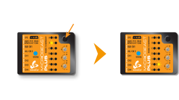
To load the preset channel assignment wait until the Status-LED lights <font color="#0066FF">'''blue'''</font> and then hold down the button for several seconds. The yellow Menu-LED will immediately jump to [[Manuals:MB_Plus:Receiver_setup_menu_N/en|Receiver menu point '''N''']].</p>
<p>
[[File:Channel_assignment.png|x200px|none]]
</p>
<p>
In case the ordering differs from the given tables, you have to manually assign the channel order step by step. How this works is described below.</p>
<p>&nbsp;</p>
<p>
{{QUOTE|* If the Status-LED stays '''red''' at menu point '''B''', this means that there is no valid remote control signal available. A channel assignment in this case is impossible! Check if the receiver is properly [[Manuals:MB_Plus:Receiver_Installation/en#Receiver_binding|bound to the transmitter]] and that a receiver/transmission protocol of the correct type is selected in [[Manuals:MB_Plus:Receiver_setup_menu_A|Receiver menu point '''A''']]. Switch off the power and restart the receiver type setup procedure from the beginning.
* You can also load the default assignment by pushing the button for several seconds in any of the following points for function assignment. This will erase all previously made individual assignments.}}</p>
{{NL}}

Preset channel assignment

For each specific type of single-line receiver selected at menu point A there is an appropriate type of receiver channel allocation saved in MICROBEAST PLUS. Please refer to the tables below. Use the column that represents your receiver type and the Status-LED color that was set at menu point A and check if your radio transmits the channels in the defined order respectively each stick function on the radio is transmitted using the specified channel number on the left. To know the channel assignment of your transmitter you can check the user manual of the transmitter or look at the servo monitor of the transmitter if it has this feature. If in doubt ask the manufacturer of your transmitter.

*Channel designation of Spektrum® transmitters:
1 2 3 4 5 6 7 8 9
THROTTLE AILERON ELEVATOR RUDDER GEAR AUX1 AUX2 AUX3 AUX4

**AttitudeControl only applicable with MICROBEAST PLUS ProEdition firmware. When using a different firmware this channel by default controls CH6 Output.
***Only applicable when RPM Governor feature is installed. Please note that the separate RPM Governor control is only used for nitro helicopters. The RPM Governor for electric helis always uses the throttle channel for governor control.


To load the preset channel assignment wait until the Status-LED lights blue and then hold down the button for several seconds. The yellow Menu-LED will immediately jump to Receiver menu point N.
In case the ordering differs from the given tables, you have to manually assign the channel order step by step. How this works is described below.


  • If the Status-LED stays red at menu point B, this means that there is no valid remote control signal available. A channel assignment in this case is impossible! Check if the receiver is properly bound to the transmitter and that a receiver/transmission protocol of the correct type is selected in Receiver menu point A. Switch off the power and restart the receiver type setup procedure from the beginning.
  • You can also load the default assignment by pushing the button for several seconds in any of the following points for function assignment. This will erase all previously made individual assignments.