Manuals:MBPlusFblV5:ReceiverType/de: Difference between revisions
Updating to match new version of source page |
Shornstein (talk | contribs) Created page with "=Vordefinierte Funktionsbelegung für Summensignalempfänger= Wenn die Steuerkanäle mittels Summensignal übertragen werden, so muss festgelegt werden welche Steuerfunktion v..." |
||
| Line 3: | Line 3: | ||
<br /> | <br /> | ||
<p> | <p>Due to the possibility of connecting very different types of receivers with different types of signal output, you must setup the receiver type in the RECEIVER MENU. Additionally when using a single-line receiver it is mandatory to define the function assignment for the receiver output channels as the single-line receiver packs the control information together and it is not clear, which channel controls which (stick) function. Finally when using a single-line receiver you have to set a failsafe position for the throttle channel. This defines at which position the motor is disabled and where to move the throttle in case the receiver is not sending any throttle signal, i.e. during power up or in case of loss of radio link.</p> | ||
<br /> | |||
{{QUOTE|By default the "Standard Receiver" is selected as receiver type. So if you're using this type of receiver and your MICROBEAST PLUS is brand new, you can skip this section as it is already setup correctly!}}<br /> | |||
<br /> | <br /> | ||
{{NL}} | {{NL}} | ||
= | =Vordefinierte Funktionsbelegung für Summensignalempfänger= | ||
Wenn die Steuerkanäle mittels Summensignal übertragen werden, so muss festgelegt werden welche Steuerfunktion von welchem Kanal angesteuert wird. Dies ist notwendig da sämtliche Steuerkanäle über eine Leitung übertragen werden und praktisch jeder Hersteller eine eigene Reihenfolge bei der Anordnung der Steuerfunktionen verwendet. Hier können die einzelnen Steuerkanäle nicht einfach durch Umstecken am Empfänger angepasst werden, so wie es bei einem „Standard Empfänger" der Fall ist. Zu jedem Fernsteuertyp ist im MICROBEAST PLUS eine vorkonfigurierte Funktionsbelegung hinterlegt, die im Verlauf der nachfolgenden Empfängereinstellung geladen werden kann.<br /> | |||
<br /> | <br /> | ||
'''Spektrum® DMS2/DSMX or JR® RJ01 DMSS remote satelite''' | |||
<p> | <p> | ||
{|cellpadding="4" cellspacing="0" border="1" | {|cellpadding="4" cellspacing="0" border="1" | ||
|- style="text-align: center; font-size: 80%;" | |- style="text-align: center; font-size: 80%;" | ||
| style="width:80px;" | | | style="width:80px;" | THR || style="width:80px;" |AIL || style="width:80px;" | ELE || style="width:80px;" | RUD || style="width:80px;" | GER || style="width:80px;" | PIT || style="width:80px;" | AX2 || style="width:80px;" | AX3 | ||
|- style="text-align: center; font-size: 80%;" | |- style="text-align: center; font-size: 80%;" | ||
| | | Throttle [CH5] || Aileron || Elevator || Rudder || Gyro gain || Pitch || Aux [CH6]* || Governor (nitro) | ||
|}</p> | |}</p> | ||
<br /> | <br /> | ||
'''PPM serial signal (SPPM)''' | |||
<p> | <p> | ||
{|cellpadding="4" cellspacing="0" border="1" | {|cellpadding="4" cellspacing="0" border="1" | ||
| Line 28: | Line 29: | ||
| style="width:80px;" | 1 || style="width:80px;" | 2 || style="width:80px;" | 3 || style="width:80px;" | 4 || style="width:80px;" | 5 || style="width:80px;" | 6 || style="width:80px;" | 7 || style="width:80px;" | 8 | | style="width:80px;" | 1 || style="width:80px;" | 2 || style="width:80px;" | 3 || style="width:80px;" | 4 || style="width:80px;" | 5 || style="width:80px;" | 6 || style="width:80px;" | 7 || style="width:80px;" | 8 | ||
|- style="text-align: center; font-size: 80%;" | |- style="text-align: center; font-size: 80%;" | ||
| Pitch || | | Pitch || Aileron || Elevator || Rudder || Aux [CH6]* || Throttle [CH5] || Gyro gain || Governor (nitro) | ||
|}</p> | |}</p> | ||
<br /> | <br /> | ||
'''Futaba® SBus/Sbus2 or BEASTX® FASST compatible receiver''' | |||
<p> | <p> | ||
{|cellpadding="4" cellspacing="0" border="1" | {|cellpadding="4" cellspacing="0" border="1" | ||
| Line 38: | Line 39: | ||
| style="width:80px;" | 1 || style="width:80px;" | 2 || style="width:80px;" | 3 || style="width:80px;" | 4 || style="width:80px;" | 5 || style="width:80px;" | 6 || style="width:80px;" | 7 || style="width:80px;" | 8 | | style="width:80px;" | 1 || style="width:80px;" | 2 || style="width:80px;" | 3 || style="width:80px;" | 4 || style="width:80px;" | 5 || style="width:80px;" | 6 || style="width:80px;" | 7 || style="width:80px;" | 8 | ||
|- style="text-align: center; font-size: 80%;" | |- style="text-align: center; font-size: 80%;" | ||
| | | Aileron || Elevator || Throttle [CH5] || Rudder || Gyro gain || Pitch || Aux [CH6]* || Governor (nitro) | ||
|}</p> | |}</p> | ||
<br /> | <br /> | ||
'''Multiplex® SRXL v1 and v2, JR® XBUS Mode B, JETI® UDI 12 + 16ch''' | |||
<p> | <p> | ||
{|cellpadding="4" cellspacing="0" border="1" | {|cellpadding="4" cellspacing="0" border="1" | ||
| Line 48: | Line 49: | ||
| style="width:80px;" | 1 || style="width:80px;" | 2 || style="width:80px;" | 3 || style="width:80px;" | 4 || style="width:80px;" | 5 || style="width:80px;" | 6 || style="width:80px;" | 7 || style="width:80px;" | 8 | | style="width:80px;" | 1 || style="width:80px;" | 2 || style="width:80px;" | 3 || style="width:80px;" | 4 || style="width:80px;" | 5 || style="width:80px;" | 6 || style="width:80px;" | 7 || style="width:80px;" | 8 | ||
|- style="text-align: center; font-size: 80%;" | |- style="text-align: center; font-size: 80%;" | ||
| | | Aileron || Elevator || Rudder || Pitch || Throttle [CH5] || Gyro gain || Aux [CH6]* || Governor (nitro) | ||
|}</p> | |}</p> | ||
<br /> | <br /> | ||
'''Graupner® SUMD''' | |||
<p> | <p> | ||
{|cellpadding="4" cellspacing="0" border="1" | {|cellpadding="4" cellspacing="0" border="1" | ||
| Line 58: | Line 59: | ||
| style="width:80px;" | 1 || style="width:80px;" | 2 || style="width:80px;" | 3 || style="width:80px;" | 4 || style="width:80px;" | 5 || style="width:80px;" | 6 || style="width:80px;" | 7 || style="width:80px;" | 8 | | style="width:80px;" | 1 || style="width:80px;" | 2 || style="width:80px;" | 3 || style="width:80px;" | 4 || style="width:80px;" | 5 || style="width:80px;" | 6 || style="width:80px;" | 7 || style="width:80px;" | 8 | ||
|- style="text-align: center; font-size: 80%;" | |- style="text-align: center; font-size: 80%;" | ||
| Pitch || | | Pitch || Aileron || Elevator || Rudder || Aux [CH6]* || Throttle [CH5] || Gyro gain || Governor (nitro) | ||
|}</p> | |}</p> | ||
<br /> | <br /> | ||
'''Spektrum® SRXL''' | |||
<p> | <p> | ||
{|cellpadding="4" cellspacing="0" border="1" | {|cellpadding="4" cellspacing="0" border="1" | ||
|- style="text-align: center; font-size: 80%;" | |- style="text-align: center; font-size: 80%;" | ||
| style="width:80px;" | | | style="width:80px;" | THR || style="width:80px;" |AIL || style="width:80px;" | ELE || style="width:80px;" | RUD || style="width:80px;" | GER || style="width:80px;" | PIT || style="width:80px;" | AX2 || style="width:80px;" | AX3 | ||
|- style="text-align: center; font-size: 80%;" | |- style="text-align: center; font-size: 80%;" | ||
| | | Throttle [CH5] || Aileron || Elevator || Rudder || Gyro gain || Pitch || Aux [CH6]* || Governor (nitro) | ||
|}</p> | |}</p> | ||
<br /> | <br /> | ||
'''Jeti® ExBus''' | |||
<p> | <p> | ||
{|cellpadding="4" cellspacing="0" border="1" | {|cellpadding="4" cellspacing="0" border="1" | ||
| Line 78: | Line 79: | ||
| style="width:80px;" | 1 || style="width:80px;" | 2 || style="width:80px;" | 3 || style="width:80px;" | 4 || style="width:80px;" | 5 || style="width:80px;" | 6 || style="width:80px;" | 7 || style="width:80px;" | 8 | | style="width:80px;" | 1 || style="width:80px;" | 2 || style="width:80px;" | 3 || style="width:80px;" | 4 || style="width:80px;" | 5 || style="width:80px;" | 6 || style="width:80px;" | 7 || style="width:80px;" | 8 | ||
|- style="text-align: center; font-size: 80%;" | |- style="text-align: center; font-size: 80%;" | ||
| | | Throttle [CH5] || Aileron || Elevator || Pitch || Rudder || Gyro gain || Aux [CH6]* || Governor (nitro) | ||
|}</p> | |}</p> | ||
<br /> | <br /> | ||
'''ALIGN®/FlySky® iBus''' | |||
<p> | <p> | ||
{|cellpadding="4" cellspacing="0" border="1" | {|cellpadding="4" cellspacing="0" border="1" | ||
| Line 88: | Line 89: | ||
| style="width:80px;" | 1 || style="width:80px;" | 2 || style="width:80px;" | 3 || style="width:80px;" | 4 || style="width:80px;" | 5 || style="width:80px;" | 6 || style="width:80px;" | 7 || style="width:80px;" | 8 | | style="width:80px;" | 1 || style="width:80px;" | 2 || style="width:80px;" | 3 || style="width:80px;" | 4 || style="width:80px;" | 5 || style="width:80px;" | 6 || style="width:80px;" | 7 || style="width:80px;" | 8 | ||
|- style="text-align: center; font-size: 80%;" | |- style="text-align: center; font-size: 80%;" | ||
| | | Aileron || Elevator || Throttle [CH5] || Rudder || Gyro gain || Pitch || Aux [CH6]* || Governor (nitro) | ||
|}</p> | |}</p> | ||
<br /> | <br /> | ||
| Line 98: | Line 99: | ||
<br /> | <br /> | ||
= | =Adjustment on the device= | ||
<p> | <p>To get into the Receiver menu press the button on MICROBEAST PLUS and hold it down before(!) and while turning on the receiver power supply. The yellow Menu-LEDs start to cycle immediately. When you release the button, Menu LED A will be flashing and the color of the Status LED will indicate the receiver type that is selected at the moment.</p> | ||
[[File:Receiver_setup_1.png|x180px|none]] | [[File:Receiver_setup_1.png|x180px|none]] | ||
{{WARNING_QUOTE| | <br /> | ||
{{WARNING_QUOTE|Note that in the first menu points of Receiver setup menu no control signal is emitted on [CH5] Output of MICROBEAST PLUS (in case you are using a single-line receiver). At Menu Point '''N''' (Throttle failsafe setting) the output is activated though to check throttle position! '''If you use a speed controller with BEC, disconnect the motor to avoid unintentional starting of the motor!''' For a heli with combustion engine you should remove the servo horn from the throttle servo to avoid linkage binding or breaking the servo horn.}}<br /> | |||
<br /> | <br /> | ||
| Line 125: | Line 127: | ||
<br /> | <br /> | ||
== | ==Points B to I (PROEDITION: J)== | ||
When using a single-line receiver it is mandatory to define the function assignment for the receiver output channels as the single-line receiver packs the control information together and it is not clear, which channel controls which (stick) function. For each specific type of receiver/radio brand there is an appropriate channel allocation preset in MICROBEAST PLUS. If this does not fit your radio system or if you like to use a different assignment or different options you can manually assign each function step by step at the Menu Points B to J. Here each point represents one function to assign.<br /> | |||
<br /> | <br /> | ||
=== | ===Default function assignment=== | ||
Refer to the tables above and identify the column that represents your receiver type. Check whether your radio transmits the channels in the given order, respectively each stick function on the radio is using the specified channel number on the left. To know the channel assignment of your transmitter you can check the user manual of the transmitter or look at the servo monitor of the transmitter. In order to load the preset channel assignment hold down the button for at least 2 seconds and release. The yellow Menu-LED will immediately jump to Menu Point '''N'''.<br /> | |||
{|style="text-align:center;" | {|style="text-align:center;" | ||
|[[File:Channel_assignment.png|x200px|none]] | |[[File:Channel_assignment.png|x200px|none]] | ||
|}<br /> | |}<br /> | ||
=== | ===Manual function assignment=== | ||
<p> | <p> | ||
In case the channel to function ordering differs from the given tables above on your radio system, you have to manually assign the channel order step by step. This is done by simply actuating the appropriate channel function on your transmitter at each of the menu points B to I (PROEDITION: J). Each menu point represents one control function to assign. When you move the control stick/adjust the channel with the transmitter, a blue flash of the Status-LED indicates that a channel has been detected. It does not matter how far or in what direction you move the stick or in what position the stick/switch was. The channels value itself is not important, but the change of this value is. It is therefore important that only the requested function is activated and not by accident several simultaneously. Otherwise MICROBEAST PLUS may not recognize the allocated channel correctly. If you have moved the wrong stick/switch, just move the correct one afterwards. MICROBEAST PLUS remembers only the last function that was operated and confirms it with blue flashing of the Status-LED.</p> | |||
Press the button after learning each function to save the assignment and to go to the next function. Once a channel was assigned, it is no longer available and is ignored by MICROBEAST PLUS for the remaining process. Thus, after learning of the collective pitch function (at Menu Point B) you can enable the throttle function (remove throttle hold or switch to a linear or V shape curve) and teach the throttle channel by re-operating the thrust stick at Menu Point G. Now the collective pitch channel is no longer considered as this channel has already been assigned previously and MICROBEAST PLUS will detect and use the throttle channel as actuator for throttle function!</p> | |||
<p> | <p>The first 6 functions must be assigned as they are necessary for the basic flight control and the button remains locked until you operate a new control function. The other functions are optional to assign and can be skipped. If special features like AttitudeControl or RPM Governor are not installed on your device, the specific menu points for assignment will not be accessible at all. | ||
* | * The assignment for Aux [CH6] Output at Menu Point H can be skipped by pressing the button without teaching a channel for this function in case it is not used. | ||
* | * Likewise, the assignment of the channel for internal nitro Governor can be skipped in case it is not needed or if you don‘t want to control the Governor with a separate channel, e. g. if your transmitter does not provide enough free channels. By skipping the assignment the internal Governor function will use a different operating mode that allows to control it via the throttle channel (set at Menu Point G) if you like. When used in an electric model the internal Governor generally is controlled with the throttle channel (set at Menu Point G). In this case the assignment at Menu Point I can be skipped anyway, as an assignment will have no effect. | ||
* | * Finally at Menu Point J you have to assign the channel that is used to activate/deactivate the AttitudeControl (only when you've installed the PROEDITION Upgrade on your device). Again this can be skipped if not needed or if you don‘t want to use a separate channel. AttitudeControl can still be used then. In this case the channel for the tail gyro sensitivity (set at Menu Point F) is used to switch AttitudeControl or you can enable it separately using the Bank Switch feature, see the section about using AttitudeControl for further details.</p> | ||
{{NL}} | {{NL}} | ||
{|cellspacing="0" cellpadding="4" border="1" style="text-align:left;" | {|cellspacing="0" cellpadding="4" border="1" style="text-align:left;" | ||
| Line 151: | Line 151: | ||
|align="center" style="color:white; background-color:rgb(244,150,0);" width="80px" | '''B''' || Collective | |align="center" style="color:white; background-color:rgb(244,150,0);" width="80px" | '''B''' || Collective | ||
|- | |- | ||
|align="center" style="color:white; background-color:rgb(244,150,0);" | '''C''' || | |align="center" style="color:white; background-color:rgb(244,150,0);" | '''C''' || Aileron | ||
|- | |- | ||
|align="center" style="color:white; background-color:rgb(244,150,0);" | '''D''' || | |align="center" style="color:white; background-color:rgb(244,150,0);" | '''D''' || Elevator | ||
|- | |- | ||
|align="center" style="color:white; background-color:rgb(244,150,0);" | '''E''' || | |align="center" style="color:white; background-color:rgb(244,150,0);" | '''E''' || Rudder | ||
|- | |- | ||
|align="center" style="color:white; background-color:rgb(244,150,0);" | '''F''' || | |align="center" style="color:white; background-color:rgb(244,150,0);" | '''F''' || Tail gyro/Bank switch | ||
|- | |- | ||
|align="center" style="color:white; background-color:rgb(244,150,0);" | '''G''' || | |align="center" style="color:white; background-color:rgb(244,150,0);" | '''G''' || Throttle [CH5] | ||
|- | |- | ||
|align="center" style="color:white; background-color:rgb(244,150,0);" | '''H''' || | |align="center" style="color:white; background-color:rgb(244,150,0);" | '''H''' || Aux Output [CH6] | ||
|- | |- | ||
|align="center" style="color:white; background-color:rgb(244,150,0);" | '''I''' || Governor ( | |align="center" style="color:white; background-color:rgb(244,150,0);" | '''I''' || Governor control (Nitro only) | ||
|- | |- | ||
|align="center" style="color:white; background-color:rgb(244,150,0);" | '''J''' || AttitudeControl | |align="center" style="color:white; background-color:rgb(244,150,0);" | '''J''' || AttitudeControl gain | ||
|}<br /> | |}<br /> | ||
<br /> | <br /> | ||
{{QUOTE| | {{QUOTE|If the Status-LED lights in '''red color''' this means either there is no valid remote control signal available or that you did try to assign two or more channels to a function. So check if the receiver is connected and powered properly and that you're only moving one channel at a time when trying to do the manual function assignment.}}<br /> | ||
<br /> | <br /> | ||
== | ==Point N - Throttle failsafe== | ||
At Menu Point N you program the failsafe position for the throttle channel. In case the single-line signal is interrupted during operation the throttle servo/speed controller connected to the [CH5] Output is automatically moved to this position. This particularly is the case: | |||
* if using a single-line receiver that turns of the single-line signal in case of signal loss between receiver and transmitter (e.g. Spektrum® satellite receiver or Graupner® receiver in „SUMDOF“ mode) | |||
* if the connection between MICROBEAST PLUS and receiver gets disconnected | |||
* | * during initialization when the transmitter was not switched on before or was switched on too late and the radio link between transmitter and receiver is not established yet | ||
* | Additionally the failsafe position is used by the internal Governor function in case you're using a helicopter with electric drive system. Here the throttle is moved to the stored failsafe position when you set the Governor to Autorotation bailout mode!<br /> | ||
* | <br /> | ||
* | '''Note:''' | ||
</ | * The fail-safe function is not effective if the receiver continues sending data even if the radio link is interrupted. In this case the failsafe setting of the remote control system may take precedence. | ||
* To avoid accidents, you should program electric motors to “off“ and reduce throttle on nitro helicopters to idle. The other control functions will be set to „position hold“ in case of signal interruption. For these setting a failsafe position is not provided.<br /> | |||
<br /> | |||
To teach the failsafe position simply set the throttle channel on your remote control to the desired position and press the button briefly. '''If you did not connect a function to CH5 Output and don't need throttle failsafe, press the button to complete setup anyway!'''<br /> | |||
<br /> | <br /> | ||
[[File:Failsafe_setup.png|noframe|none|x180px]]<br /> | |||
[[File:Failsafe_setup.png|noframe|none| | |||
<br /> | <br /> | ||
{{WARNING_QUOTE|''' | {{WARNING_QUOTE|'''During failsafe setting the CH5 Output is enabled and can be controlled by the transmitter channel that is assigned to throttle function.''' This allows to check your throttle position in reality. When using electric models make sure the motor is disconnected from the ESC or the pinion is removed from the motor, so that it will not drive the model by accident. | ||
}}<br /> | }}<br /> | ||
<br /> | |||
<br /> | <br /> | ||
= | =Setup with StudioX= | ||
When StudioX is started and your MICROBEAST PLUS was detected by StudioX click the Control Setup tab to show the adjustment options of RECEIVER MENU. The options you see here are basically similar to the Menu Points you can change directly at the device. In the first row (Menu Point A) you can see which type of receiver/input signal is selected at the moment. The rows below show what channels are assigned to which control functions. Finally in the last row (Menu Point N) you can what value for throttle failsafe position is set in the device.<br /> | |||
<br /> | <br /> | ||
{|class="gallery" style="font-style: italic" | |||
|- | |||
|width="400pt" style="padding:0px 0px;" align="left"|[[File:ClickControlSetup.png|x250px]] | |||
|}<br /> | |||
<br /> | <br /> | ||
Revision as of 12:10, 2 January 2018
Due to the possibility of connecting very different types of receivers with different types of signal output, you must setup the receiver type in the RECEIVER MENU. Additionally when using a single-line receiver it is mandatory to define the function assignment for the receiver output channels as the single-line receiver packs the control information together and it is not clear, which channel controls which (stick) function. Finally when using a single-line receiver you have to set a failsafe position for the throttle channel. This defines at which position the motor is disabled and where to move the throttle in case the receiver is not sending any throttle signal, i.e. during power up or in case of loss of radio link.
By default the "Standard Receiver" is selected as receiver type. So if you're using this type of receiver and your MICROBEAST PLUS is brand new, you can skip this section as it is already setup correctly!
Vordefinierte Funktionsbelegung für Summensignalempfänger
Wenn die Steuerkanäle mittels Summensignal übertragen werden, so muss festgelegt werden welche Steuerfunktion von welchem Kanal angesteuert wird. Dies ist notwendig da sämtliche Steuerkanäle über eine Leitung übertragen werden und praktisch jeder Hersteller eine eigene Reihenfolge bei der Anordnung der Steuerfunktionen verwendet. Hier können die einzelnen Steuerkanäle nicht einfach durch Umstecken am Empfänger angepasst werden, so wie es bei einem „Standard Empfänger" der Fall ist. Zu jedem Fernsteuertyp ist im MICROBEAST PLUS eine vorkonfigurierte Funktionsbelegung hinterlegt, die im Verlauf der nachfolgenden Empfängereinstellung geladen werden kann.
Spektrum® DMS2/DSMX or JR® RJ01 DMSS remote satelite
| THR | AIL | ELE | RUD | GER | PIT | AX2 | AX3 |
| Throttle [CH5] | Aileron | Elevator | Rudder | Gyro gain | Pitch | Aux [CH6]* | Governor (nitro) |
PPM serial signal (SPPM)
| 1 | 2 | 3 | 4 | 5 | 6 | 7 | 8 |
| Pitch | Aileron | Elevator | Rudder | Aux [CH6]* | Throttle [CH5] | Gyro gain | Governor (nitro) |
Futaba® SBus/Sbus2 or BEASTX® FASST compatible receiver
| 1 | 2 | 3 | 4 | 5 | 6 | 7 | 8 |
| Aileron | Elevator | Throttle [CH5] | Rudder | Gyro gain | Pitch | Aux [CH6]* | Governor (nitro) |
Multiplex® SRXL v1 and v2, JR® XBUS Mode B, JETI® UDI 12 + 16ch
| 1 | 2 | 3 | 4 | 5 | 6 | 7 | 8 |
| Aileron | Elevator | Rudder | Pitch | Throttle [CH5] | Gyro gain | Aux [CH6]* | Governor (nitro) |
Graupner® SUMD
| 1 | 2 | 3 | 4 | 5 | 6 | 7 | 8 |
| Pitch | Aileron | Elevator | Rudder | Aux [CH6]* | Throttle [CH5] | Gyro gain | Governor (nitro) |
Spektrum® SRXL
| THR | AIL | ELE | RUD | GER | PIT | AX2 | AX3 |
| Throttle [CH5] | Aileron | Elevator | Rudder | Gyro gain | Pitch | Aux [CH6]* | Governor (nitro) |
Jeti® ExBus
| 1 | 2 | 3 | 4 | 5 | 6 | 7 | 8 |
| Throttle [CH5] | Aileron | Elevator | Pitch | Rudder | Gyro gain | Aux [CH6]* | Governor (nitro) |
ALIGN®/FlySky® iBus
| 1 | 2 | 3 | 4 | 5 | 6 | 7 | 8 |
| Aileron | Elevator | Throttle [CH5] | Rudder | Gyro gain | Pitch | Aux [CH6]* | Governor (nitro) |
Modified assignment with PROEDITION firmware (*)
When using the PROEDITION Firmware upgrade by default the channel for function Aux [CH6] will be used to control the AttidudeControl gain. The control for Aux [CH6] will be moved to channel 9 (or AX4 for Spektrum® radios).
Please note: When you don't want to use a separate channel to control the AttitudeGain or when your radio doesn't have a sufficient amount of output channels, you have to skip the assignment for the AttitudeControl function manually!
Adjustment on the device
To get into the Receiver menu press the button on MICROBEAST PLUS and hold it down before(!) and while turning on the receiver power supply. The yellow Menu-LEDs start to cycle immediately. When you release the button, Menu LED A will be flashing and the color of the Status LED will indicate the receiver type that is selected at the moment.

Note that in the first menu points of Receiver setup menu no control signal is emitted on [CH5] Output of MICROBEAST PLUS (in case you are using a single-line receiver). At Menu Point N (Throttle failsafe setting) the output is activated though to check throttle position! If you use a speed controller with BEC, disconnect the motor to avoid unintentional starting of the motor! For a heli with combustion engine you should remove the servo horn from the throttle servo to avoid linkage binding or breaking the servo horn.
Einstellpunkt A - Empfängertyp
Damit der angesteckte Empfängertyp erkannt werden kann, muss der Fernsteuersender eingeschaltet und mit dem Empfänger gebunden sein. Stelle auch sicher, dass die Grundeinstellung des Sender wie im Kapitel Fersteuersystem beschrieben durchgeführt wurde. Drücke dann bei Einstellpunkt A einfach einmal kurz auf den Knopf, um den Scan-Vorgang zu starten. Die Farbe der Status LED gibt jeweils an, nach welchem Empfängertyp gerade gesucht wird. Sobald der entsprechende Typ erkannt wurde, wird dieser abgespeichert und die Einstellprozedur springt automatisch zu Einstellpunkt B, falls ein Summensignal -Empfänger verwendet wird. Wenn ein Standardempfänger verwendet wird, ist soweit alles Notwendige einstellt und das EMPFÄNGER MENÜ wird geschlossen.
Falls die Empfängersuche fehlschlägt, wird das System bei Einstellpunkt A bleiben und die Status LED signalisiert mit rotem Blinken, dass kein passender Typ gefunden wurde. Sollte das passieren, überprüfe nochmal ob alles korrekt angeschlossen ist, der Sender korrekt mit dem Empfänger zusammenarbeitet, die Versorgungsspannung ausreichend ist und ob der Empfänger tatsächlich die Steuersignale ausgibt und ob es sich um ein unterstützes Datenformat handelt.
| Status-LED | Empfängertyp/Übertragungsprotokoll |
|---|---|
| aus | Spektrum®/JR® Einzelsatellit |
| violett | SPPM (PPM Summensignal) |
| rot | Serielles Datensignal |
| blau | Standard Empfänger |
Points B to I (PROEDITION: J)
When using a single-line receiver it is mandatory to define the function assignment for the receiver output channels as the single-line receiver packs the control information together and it is not clear, which channel controls which (stick) function. For each specific type of receiver/radio brand there is an appropriate channel allocation preset in MICROBEAST PLUS. If this does not fit your radio system or if you like to use a different assignment or different options you can manually assign each function step by step at the Menu Points B to J. Here each point represents one function to assign.
Default function assignment
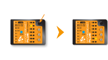
Refer to the tables above and identify the column that represents your receiver type. Check whether your radio transmits the channels in the given order, respectively each stick function on the radio is using the specified channel number on the left. To know the channel assignment of your transmitter you can check the user manual of the transmitter or look at the servo monitor of the transmitter. In order to load the preset channel assignment hold down the button for at least 2 seconds and release. The yellow Menu-LED will immediately jump to Menu Point N.
 |
Manual function assignment
In case the channel to function ordering differs from the given tables above on your radio system, you have to manually assign the channel order step by step. This is done by simply actuating the appropriate channel function on your transmitter at each of the menu points B to I (PROEDITION: J). Each menu point represents one control function to assign. When you move the control stick/adjust the channel with the transmitter, a blue flash of the Status-LED indicates that a channel has been detected. It does not matter how far or in what direction you move the stick or in what position the stick/switch was. The channels value itself is not important, but the change of this value is. It is therefore important that only the requested function is activated and not by accident several simultaneously. Otherwise MICROBEAST PLUS may not recognize the allocated channel correctly. If you have moved the wrong stick/switch, just move the correct one afterwards. MICROBEAST PLUS remembers only the last function that was operated and confirms it with blue flashing of the Status-LED.
Press the button after learning each function to save the assignment and to go to the next function. Once a channel was assigned, it is no longer available and is ignored by MICROBEAST PLUS for the remaining process. Thus, after learning of the collective pitch function (at Menu Point B) you can enable the throttle function (remove throttle hold or switch to a linear or V shape curve) and teach the throttle channel by re-operating the thrust stick at Menu Point G. Now the collective pitch channel is no longer considered as this channel has already been assigned previously and MICROBEAST PLUS will detect and use the throttle channel as actuator for throttle function!
The first 6 functions must be assigned as they are necessary for the basic flight control and the button remains locked until you operate a new control function. The other functions are optional to assign and can be skipped. If special features like AttitudeControl or RPM Governor are not installed on your device, the specific menu points for assignment will not be accessible at all.
- The assignment for Aux [CH6] Output at Menu Point H can be skipped by pressing the button without teaching a channel for this function in case it is not used.
- Likewise, the assignment of the channel for internal nitro Governor can be skipped in case it is not needed or if you don‘t want to control the Governor with a separate channel, e. g. if your transmitter does not provide enough free channels. By skipping the assignment the internal Governor function will use a different operating mode that allows to control it via the throttle channel (set at Menu Point G) if you like. When used in an electric model the internal Governor generally is controlled with the throttle channel (set at Menu Point G). In this case the assignment at Menu Point I can be skipped anyway, as an assignment will have no effect.
- Finally at Menu Point J you have to assign the channel that is used to activate/deactivate the AttitudeControl (only when you've installed the PROEDITION Upgrade on your device). Again this can be skipped if not needed or if you don‘t want to use a separate channel. AttitudeControl can still be used then. In this case the channel for the tail gyro sensitivity (set at Menu Point F) is used to switch AttitudeControl or you can enable it separately using the Bank Switch feature, see the section about using AttitudeControl for further details.
| Menu point | Function |
|---|---|
| B | Collective |
| C | Aileron |
| D | Elevator |
| E | Rudder |
| F | Tail gyro/Bank switch |
| G | Throttle [CH5] |
| H | Aux Output [CH6] |
| I | Governor control (Nitro only) |
| J | AttitudeControl gain |
If the Status-LED lights in red color this means either there is no valid remote control signal available or that you did try to assign two or more channels to a function. So check if the receiver is connected and powered properly and that you're only moving one channel at a time when trying to do the manual function assignment.
Point N - Throttle failsafe
At Menu Point N you program the failsafe position for the throttle channel. In case the single-line signal is interrupted during operation the throttle servo/speed controller connected to the [CH5] Output is automatically moved to this position. This particularly is the case:
- if using a single-line receiver that turns of the single-line signal in case of signal loss between receiver and transmitter (e.g. Spektrum® satellite receiver or Graupner® receiver in „SUMDOF“ mode)
- if the connection between MICROBEAST PLUS and receiver gets disconnected
- during initialization when the transmitter was not switched on before or was switched on too late and the radio link between transmitter and receiver is not established yet
Additionally the failsafe position is used by the internal Governor function in case you're using a helicopter with electric drive system. Here the throttle is moved to the stored failsafe position when you set the Governor to Autorotation bailout mode!
Note:
- The fail-safe function is not effective if the receiver continues sending data even if the radio link is interrupted. In this case the failsafe setting of the remote control system may take precedence.
- To avoid accidents, you should program electric motors to “off“ and reduce throttle on nitro helicopters to idle. The other control functions will be set to „position hold“ in case of signal interruption. For these setting a failsafe position is not provided.
To teach the failsafe position simply set the throttle channel on your remote control to the desired position and press the button briefly. If you did not connect a function to CH5 Output and don't need throttle failsafe, press the button to complete setup anyway!
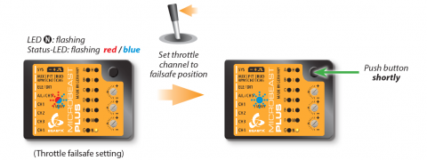
During failsafe setting the CH5 Output is enabled and can be controlled by the transmitter channel that is assigned to throttle function. This allows to check your throttle position in reality. When using electric models make sure the motor is disconnected from the ESC or the pinion is removed from the motor, so that it will not drive the model by accident.
Setup with StudioX
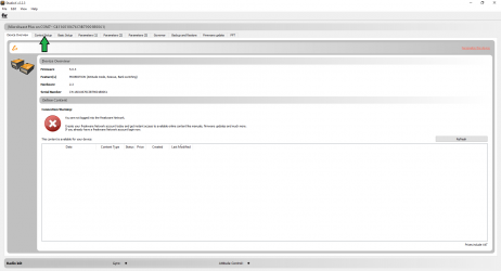
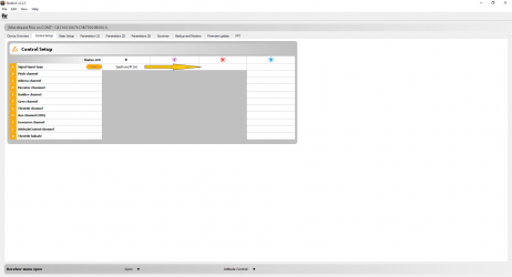
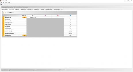
When StudioX is started and your MICROBEAST PLUS was detected by StudioX click the Control Setup tab to show the adjustment options of RECEIVER MENU. The options you see here are basically similar to the Menu Points you can change directly at the device. In the first row (Menu Point A) you can see which type of receiver/input signal is selected at the moment. The rows below show what channels are assigned to which control functions. Finally in the last row (Menu Point N) you can what value for throttle failsafe position is set in the device.
|
Point A - Receiver type
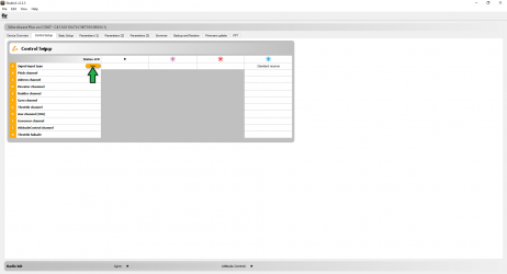
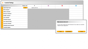
In order to detect the connected receiver type make sure the receiver is bound to the transmitter and sending out signals. Also make sure the transmitter is setup correctly as shown in the chapter Radio System. Press the "Scan" button to start automatic receiver detection routine. The Status-LED on the device and the display will indicate which type the system is scanning for at the moment. When a valid input signal was detected the receiver type will be set automatically and a small dialog will appear and ask you how to proceed with function assignments in case a single-line receiver is used or the system will restart when a Standard receiver is used. When detection fails the system will stay at menu point A. In this case once again make sure your receiver is connected properly to MICROBEAST PLUS, bound to the transmitter and sending out control signals and try again.
|
|
|
Points B to I (PROEDITION: J)
When using a single-line receiver it is mandatory to define the function assignment for the receiver output channels as the single-line receiver packs the control information together and it is not clear, which channel controls which (stick) function. For each specific type of receiver/radio brand there is an appropriate channel allocation preset in MICROBEAST PLUS. If this does not fit your radio system or if you like to use a different assignment or different options you can manually assign each function step by step at the Menu Points B to I (J). Here each point represents one function to assign.
Default function assignment
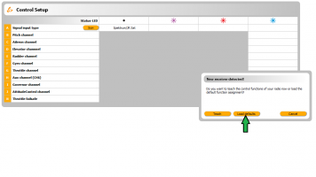
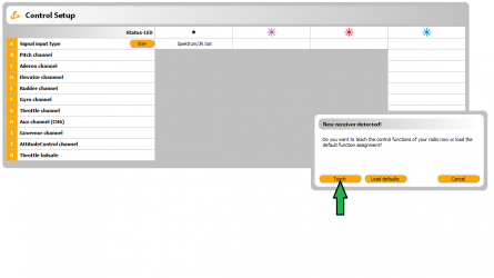
Refer to the tables above and identify the column that represents your receiver type. Check whether your radio transmits the channels in the given order, respectively each stick function on the radio is using the specified channel number on the left. To know the channel assignment of your transmitter you can check the user manual of the transmitter or look at the servo monitor of the transmitter. In order to load the preset assignment choose Load defaults from the "New receiver detected!" dialog. Immediately after that the "Failsafe" dailog will show up.
|
|
Manual function assignment
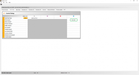
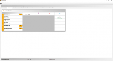
In case the channel to function ordering differs from the given tables above on your radio system, you have to manually assign the channel order step by step. This is done by simply actuating the appropriate channel function on your transmitter at each of the menu points B to I (PROEDITION: J). Each menu point represents one control function to assign. When you're ready click Teach in the "New receiver detected!" dialog and start with function allocation at Menu Point B. When you move the control stick/adjust the channel on the transmitter, a blue flash of the Status-LED indicates that the channel has been detected. The setup will jump to the next menu point automatically. It does not matter how far or in what direction you move the stick or in what position the stick/switch was. The channel's value itself is not important, but the change of this value is. It is therefore important that only the requested function is activated and not by accident several simultaneously. Otherwise MICROBEAST PLUS may not recognize the allocated channel correctly. Once a channel was assigned, it is no longer available and is ignored by MICROBEAST PLUS for the remaining process. Thus, after learning of the collective pitch function (at Menu Point B) you can enable the throttle function (remove throttle hold or switch to a linear or V shape curve) and teach the throttle channel by re-operating the thrust stick at Menu Point G. Now the collective pitch channel is no longer considered as this channel has already been assigned previously and MICROBEAST PLUS will detect and use the throttle channel as actuator for throttle function!
|
|
|
The first 6 functions must be assigned as they are necessary for the basic flight control and the button remains locked until you operate a new control function. The other functions are optional to assign and can be skipped. If special features like AttitudeControl or RPM Governor are not installed on your device, the specific menu points for assignment will not be accessible at all.
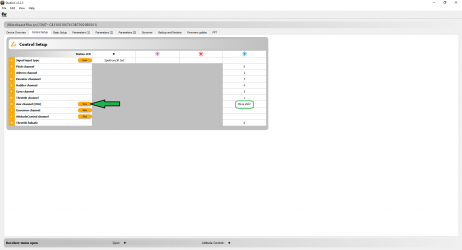
- The assignment for Aux [CH6] Output at Menu Point H can be skipped by pressing the "Skip" button without teaching a channel for this function in case it is not used.
- Likewise, the assignment of the channel for internal nitro Governor can be skipped in case it is not needed or if you don‘t want to control the Governor with a separate channel, e. g. if your transmitter does not provide enough free channels. By skipping the assignment the internal Governor function will use a different operating mode that allows to control it via the throttle channel (set at Menu Point G) if you like. When used in an electric model the internal Governor generally is controlled with the throttle channel (set at Menu Point G). In this case the assignment at Menu Point I can be skipped anyway, as an assignment will have no effect.
- Finally at Menu Point J you have to assign the channel that is used to activate/deactivate the AttitudeControl (only when you've installed the PROEDITION Upgrade on your device). Again this can be skipped if not needed or if you don‘t want to use a separate channel. AttitudeControl can still be used then. In this case the channel for the tail gyro sensitivity (set at Menu Point F) is used to switch AttitudeControl or you can enable it separately using the Bank Switch feature, see the section about using AttitudeControl for further details.
|
|
If the Status-LED lights in red color this means either there is no valid remote control signal available or that you did try to assign two or more channels to a function. So check if the receiver is connected and powered properly and that you're only moving one channel at a time when trying to do the manual function assignment.
Point N - Throttle failsafe
After you've set the control functions you will reach Menu Point N to program the failsafe position for the throttle channel. In case the single-line signal is interrupted during operation the throttle servo/speed controller connected to the [CH5] Output is automatically moved to this position. This particularly is the case:
- if using a single-line receiver that turns of the single-line signal in case of signal loss between receiver and transmitter (e.g. Spektrum® satellite receiver or Graupner® receiver in „SUMDOF“ mode)
- if the connection between MICROBEAST PLUS and receiver gets disconnected
- during initialization when the transmitter was not switched on before or was switched on too late and the radio link between transmitter and receiver is not established yet
Additionally the failsafe position is used by the internal Governor function in case you're using a helicopter with electric drive system. Here the throttle is moved to the stored failsafe position when you set the Governor to Autorotation bailout mode!
Note:
- The fail-safe function is not effective if the receiver continues sending data even if the radio link is interrupted. In this case the failsafe setting of the remote control system may take precedence.
- To avoid accidents, you should program electric motors to “off“ and reduce throttle on nitro helicopters to idle. The other control functions will be set to „position hold“ in case of signal interruption. For these setting a failsafe position is not provided.
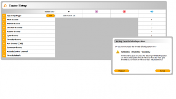
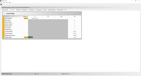
To teach the failsafe position choose "Proceed" when asked to teach the failsafe position and set the throttle channel on your remote control to the desired position. Then press Set to save the position. If you did not connect a function to CH5 Output and don't need throttle failsafe, press Cancel to complete setup!

|
|
During failsafe setting the CH5 Output is enabled and can be controlled by the transmitter channel that is assigned to throttle function. This allows to check your throttle position in reality. When using electric models make sure the motor is disconnected from the ESC or the pinion is removed from the motor, so that it will not drive the model by accident.
Einstellung mit StudioXm
