Translations:Manuals:MBPlusFblV52:Radio System/4/en: Difference between revisions
Importing a new version from external source |
Importing a new version from external source |
||
| Line 1: | Line 1: | ||
=Standard receiver= | =Standard receiver= | ||
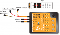
A conventional receiver with multiple servo output connectors is what we consider a "Standard receiver". Here you connect each | A conventional receiver with multiple servo output connectors is what we consider a "Standard receiver". Here you connect each output to one control function of MICROBEAST PLUS by using one connection wire for each function. The 5 control functions (wires) are: Aileron, Elevator, Rudder, Collective pitch and Gyro gain. Connect each wire to the corresponding servo output at the receiver which you like to use for the specific function. If you don't know which stick controls which channel have a look at your radio's servo monitor, refer to your radios instruction manual or simply connect a servo to each channel testwise!<br /> | ||
<br /> | <br /> | ||
{|cellspacing = "20" | {|cellspacing = "20" | ||
|style="text-align:center;"| [[Image:Standard_RX.png|250px]] | |style="text-align:center;"| [[Image:Standard_RX.png|250px]] | ||
|}<br /> | |}<br /> | ||
Here we show connection layouts for two common radio brands. Note that this is only exemplary, the channel output of your transmitter can by different even when using a radio of this brand. And you can use any | Here we show connection layouts for two common radio brands. Note that this is only exemplary, the channel output of your transmitter can by different even when using a radio of this brand. And you can use any radio system on the market, not only these two brands! | ||
{|cellspacing = "20" | {|cellspacing = "20" | ||
|[[Image:Spektrum_RX.png|x100px]] | |[[Image:Spektrum_RX.png|x100px]] | ||
| Line 12: | Line 12: | ||
{{QUOTE| | {{QUOTE| | ||
* The wires for rudder, pitch and gyro are signal wires. They must be placed on the same receiver side as the the both orange wires from aileron and elevator! | * The wires for rudder, pitch and gyro are signal wires. They must be placed on the same receiver side as the the both orange wires from aileron and elevator! | ||
* You must connect all 5 functions/wires to the receiver. When you | * You must connect all 5 functions/wires to the receiver. When you don't connect all wires, the system will not finish initialization sequence! | ||
* The throttle servo/speed controller is connected to the receiver's throttle output. Using the | * The throttle servo/speed controller is connected to the receiver's throttle output. Using the headspeed governor function of MICROBEAST PLUS is not possible in combination with a Standard receiver!}}<br /> | ||
<br /> | <br /> | ||
<br /> | <br /> | ||
Revision as of 08:01, 1 October 2020
Standard receiver
A conventional receiver with multiple servo output connectors is what we consider a "Standard receiver". Here you connect each output to one control function of MICROBEAST PLUS by using one connection wire for each function. The 5 control functions (wires) are: Aileron, Elevator, Rudder, Collective pitch and Gyro gain. Connect each wire to the corresponding servo output at the receiver which you like to use for the specific function. If you don't know which stick controls which channel have a look at your radio's servo monitor, refer to your radios instruction manual or simply connect a servo to each channel testwise!

|
Here we show connection layouts for two common radio brands. Note that this is only exemplary, the channel output of your transmitter can by different even when using a radio of this brand. And you can use any radio system on the market, not only these two brands!

|

|
- The wires for rudder, pitch and gyro are signal wires. They must be placed on the same receiver side as the the both orange wires from aileron and elevator!
- You must connect all 5 functions/wires to the receiver. When you don't connect all wires, the system will not finish initialization sequence!
- The throttle servo/speed controller is connected to the receiver's throttle output. Using the headspeed governor function of MICROBEAST PLUS is not possible in combination with a Standard receiver!