SETUPMENÜ H - Mittentrimmung Taumelscheibe
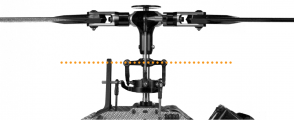
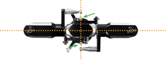
Bei SETUP MENU Punkt H werden die Mittenpositionen der Servos elektronisch nachjustiert, so dass die Servohebel im richtigen Winkel zum Anlenkgestänge stehen (üblicherweise exakt 90 Grad). Dieser Schritt ist notwendig, weil es normalerweise nicht gelingen wird, die Servohebel in genau dieser Position auf das Servo aufzustecken. Wenn alle Servos passend eingestellt sind, springe bitte noch nicht zum nächsten Einstellschritt! Prüfe ob die Anlenkgestänge entsprechend der Anleitung des Helis korrekt eingestellt sind und stelle ihre Länge falls notwendig passend ein. Die Taumelscheibe muss mittig und im rechten Winkel zur Hauptrotorwelle ausgerichtet sein und die Rotorblätter sollten 0° Pitchanstellwinkel haben. Stellen erst die unteren Gestänge ein, so dass die Taumelscheibe perfekt ausgerichtet ist und justiere dann den Anstellwinkel der Rotorblätter mittels der Anlenkgestänge zwischen Taumelscheibe und Blatthalter. Achte auch auf korrekte Ausrichtung des Taumelscheibenmitnehmers, falls vorhanden! Bei 0° Pitch sollten die Mitnehmerarme horizontal stehen und die Kugeln für die Blatthalteranlenkgestänge müssen exakt 90° zu Blattlagerwelle stehen.

|

|
Adjustment on the device
Initially when the trimming is 0 on all servos the Status LED will be off. Attach the servo horns on the servos at their true center position, so that you get roughly equal throws to both direction. Mount the servo horns so that they form as much as possible a 90 degrees angle to the linkage rod. Then in the next step you electronically fine trim every single servo‘s center position, as usually mounting the servo horn at exact 90 degrees will not work out perfectly depending on the servo‘s gear train and the servo horn.
By tapping the aileron stick you can select one servo after another. Every color of the Status-LED is corresponding to a specific servo channel that is indicating its selection by a short up and down move. Use the rudder stick to change the servo trimming/adjust the center position. You can switch back and forth between the servos as often as you need.
| Status-LED | Servo trim |
| off | all zero |
| purple | CH1 – elevator servo |
| red | CH2 – aileron(1) servo |
| blue | CH3 – aileron(2) / pitch servo (mCCPM) |
| red/blue | CH7 – elevator servo(2) (90° eCCPM only) |
Setup with StudioX
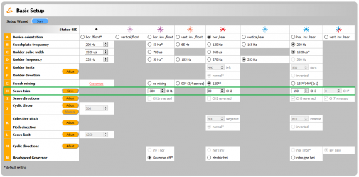
To activate the servo trim adjustments click the Adjust button in the corresponding table row (when using the Wizard function this will be done automatically when you click the Next button after adjusting Menu Point G). For your reference the servos will briefly move up and down once one after another in the given order CH1 to CH3 (CH7) so you can identify them easily. Trim each servo so that the servo horn forms an exact 90 degrees angle with the linkage rod. Then make the mechanical adjustment for the linkages as described above if necessary. Finally click the Save button or Next button (when using the Wizard function) to finish the servo trim adjustment.
Setup with StudioXm
When the servo trim screen appears, for your reference the servos will briefly move up and down once one after another in the given order CH1 to CH3 (CH7) so you can identify them easily. Trim each servo using the + and - buttons so that the servo horn forms an exact 90 degrees angle with the linkage rod. Then make the mechanical adjustment for the linkages as described above if necessary.
File:SetupHm.png
