FRSky S.Port & F.Port
FRSky bietet eine große Auswahl an verschiedenen Empfängern und Datenprotokollen, so dass es sehr schwierig ist, den Überblick über alle diese Protokolle zu behalten. Glücklicherweise gibt es einige grundlegende Protokolle, die alle Empfänger und Fernsteuerungen unterstützen, so dass es möglich sein sollte, eine funktionierende Lösung in Kombination mit dem BEASTX System zu finden.
SBUS
Normalerweise können alle Empfänger die Steuerdaten per Futaba SBUS Datenprotokoll senden. Da die BEASTX Systeme Futaba SBUS schon seit vielen Jahren unterstützen, ist das die einfachste Lösung. Verbinden hierzu den SBUS Ausgang des Empfängers mit dem DI1/IO1-Port Deines BEASTX Systems und schon kann es losgehen.
S.Port (inv.)
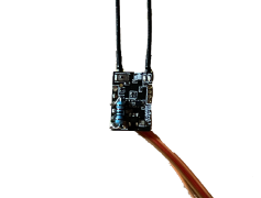
Wenn es darum geht, Telemetriedaten zurück zum Empfänger zu senden, wird es komplizierter. Es gibt ein älteres Protokoll namens S.PORT, das es ermöglicht, Telemetriedaten über eine zweite Leitung zurück zum Empfänger zu senden. Dies wurde vorwiegend für RC Drohnen eingeführt. Ein Problem hierbei ist, dass das Signal elektrisch invertiert ist, ähnlich wie es bei Futaba SBUS gemacht wird. Da die meisten Flugsteuerungen jedoch standardmäßig keine Signalinverter am Ausgang haben, hat FRSky ein invertiertes S.Port Signal bei einigen ihrer Empfänger hinzugefügt. So kann das Signal als "normales" UART Protokoll gelesen werden, womit die meisten Flugsteuerungen arbeiten können. Wenn Du einen dieser Empfänger hast, kannst Du ihn im Normalfall in Kombination mit MICROBEAST PLUS / ULTRA und NANOBEAST verwenden. Bitte beachte, dass Du hierzu einen zusätzlichen 10kOhm Widerstand zwischen Signalleitung und Masse/Minus hinzufügen müssen, um das Signal zu stabilisieren!
|
|
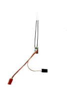
| Archer RS+ mit SBUS und S.Port(inv.) Signal | 10kOhm Widerstand zwischen S.Port (inv.) und Minus |
F.Port
Dann gibt es auch noch F.Port, das im Jahr 2020 eingeführt wurde. Hier werden Telemetriedaten und Steuerdaten zu einer Datenleitung kombiniert. Dieses System wurde dann noch zu F.Port2 weiterentwickelt, manchmal auch als FBUS bezeichnet. Aktuell unterstützt MICROBEAST ULTRA das originale F.PORT, das soweit wir wissen bei jedem neueren FRSky Empfänger verfügbar ist. MICROBEAST PLUS / NANOBEAST können aufgrund der elektrischen Architektur (bidirektionales invertiertes Busprotokoll) das F.Port Protokoll leider nicht unterstützen, .
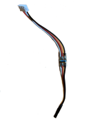
Bitte beachte, dass du möglicherweise einen zusätzlichen Widerstand von 4,7kOhm bis 10kOhm zwischen der Signalleitung und Masse/Minus hinzufügen musst, um das Signal zu stabilisieren! Es kann auch ohne Widerstand funktionieren. Wenn das Telemetriesignal allerdings nicht stabil ist, wird ein Widerstand helfen.

|
|
| 4,7kOhm Widerstand zwischen Signal und Minus | Eine kleine Leiterplatte kann das Löten erleichtern |
Connection scheme
| DI1/IO1 | CH5/IO2 | SYS | SAT | DI2 | Note |
|---|---|---|---|---|---|
| SBUS | - | - | - | - | |
| SBUS | - | S.Port (inv.) | ESC telemetry | - | |
| - | ESC telemetry | F.Port | - | - | only MB ULTRA |
| - | ESC telemetry | - | - | F.Port | only MB ULTRA |
S.Port
The wire for ESC control is connected to [CH5] at MICROBEAST PLUS, to [IO2] at MICROBEAST ULTRA and to [CH1] at NANOBEAST.
In order to use SYS for connecting the BLE2SYS / USBSYS for using the StudioX app, simply disconnect the receiver's S.PORT from SYS temporarily, switch off your radio and power cycle your device. It will then enable "normal" SYS operation for programming purpose.
F.Port
The wire for ESC control is connected to [IO1] at MICROBEAST ULTRA. The wire for the ESC telemetry signal is connected to [CH5/IO2].
When using [SYS] for the F.Port signal, you must connect the BLE2SYS / USB2SYS adapter at the DI2 port in order to use the StudioX app. Here you need the Telemetry adapter cable BXA76406 from standard servo connector to 5-pin JST. Alternatively you can simply disconnect the F.PORT signal from SYS temporarily, switch off your radio and power cycle your device. It will then enable "normal" SYS operation for programming purpose. Please note that in this case you will not be able to control the system from the radio during setup with StudioX.
Radio setup
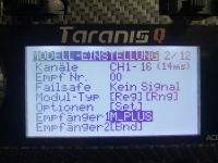
To enable the S.Port or F.Port output scroll down to the MODEL MENU on your FRSKY radio and select the receiver output accordingly.
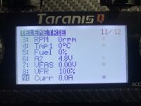
If telemetry data is received you should see all available data when starting the SCAN PROCESS in TELEMETRY MENU of your FRSky radio.
|
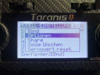
|
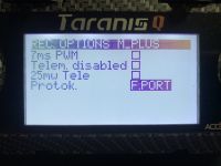
|
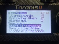
|
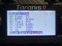
|
|
BEASTX setup
In order to use your FRSKY receiver you have to scan the input type in the RECEIVER MENU of your BEASTX device and set the correct channel ordering
for your radio system. We use the channel layout that is also used on FUTABA radio: AETR. You can change the channel layout in the MODEL MENU on your FRSKY radio.
| Channel | Function |
|---|---|
| CH1 | Roll / Aileron |
| CH2 | Pitch / Elevator |
| CH3 | Throttle |
| CH4 | Rudder |
| CH5 | Gain |
| CH6 | Thrust / Collective |
| CH7 | AttitudeControl (optional) |
| CH8 | Governor (optional) |
| CH9 | Aux channel (optional) |
(The optional functions are described in the section Optional features.)
MICROBEAST PLUS / MICROBEAST ULTRA
Push and hold the button on your MICROBEAST and power up the device. Menu LED A will flash instantly. Now release the button. Push again to start the scan process. When scan was successful, Menu LED B will show up. Now push and hold the button for 2 seconds and release in order to load the default channel assignments. If needed you can set up telemetry at Menu LEDs L & M, if applicable; push button briefly to skip. Finally teach throttle failsafe position at Menu LED N by bringing the throttle in lowest position on your radio and push the button again. Now your MICROBEAST will start with init sequence. You can perform basic setup procedure in SETUP MENU when init sequence was completed. For further information about RECEIVER MENU setup, see next section.
NANOBEAST
Connect the SBUS signal of the receiver to [DI1] port and power up NANOBEAST. Connect the push button to [SYS] port. Push and hold the button for 2 seconds, then release. The Status LED will change color or go off. Push the button again to start the scan process. When scan was successful, the Status LED will flash twice. Now push and hold the button for 2 seconds and release in order to load the default channel assignments. If needed you can set up telemetry at Menus L & M, if applicable (Menu L = Status LED flashes long once and then 5 times, for Menu L 6 times); push button briefly to skip. Finally teach throttle failsafe position at Menu N (Status LED flashes long once and then 7 times) by bringing the throttle in lowest position on your radio and push the button again. Now your NANOBEAST will start with init sequence. For further information about RECEIVER MENU setup, see next section. Then perform basic setup procedure in SETUP MENU.
Setup with StudioX
You can also use the StudioX app to start receiver scan and perform further setup steps. In this case open the Control menu in StudioX and click the SCAN button in this menu's screen. For further informations please refer to the StudioX instruction notes.
Please note that when using S.PORT (inv.) telemetry connected to [SYS], you must disconnect the receiver from [SYS] temporarily, switch off your radio and power cycle your device. It will then enable "normal" [SYS] operation for programming purpose. When using F.Port connected at [SYS] in combination with MICROBEAST ULTRA you can connect your BLE2SYS/USB2SYS at the DI2 port at the side of the device using the Telemetry adapter cable BXA76406.