EMPFÄNGERMENÜ - Telemetrie
Das MICROBEAST PLUS bietet ab Firmware-Version 5.4.x die Möglichkeit, Telemetriedaten von telemetriefähigen Endgeräten an den Empfänger weiterzuleiten, damit die Daten im Fernsteuersender angezeigt werden. Da es keine einheitlichen Spezifikationen für Telemetrieprotokolle gibt, fungiert das MICROBEAST PLUS als Middleware zwischen den Systemen. Es werden eine Vielzahl unterschiedlicher Datenprotokolle unterstützt, die intern in ein einheitliches Format umgewandelt und dann für das empfangende Fernsteuersystem übersetzt und aufbereitet werden. Die typische Anwendung ist die Übertragung von Akku- und Motordaten vom Motorsteller (Batteriespannung, Stromaufnahme, Stromverbrauch,FET-Temperatur, ...). So erhält der Pilot detaillierte Einblicke und weiß, wann es Zeit ist, zu landen.
Folgende Motorsteller/Sensoren werden derzeit unterstützt:
- Hobbywing® Platinum (V4/V5)
- Kontronik® JIVE/PowerJIVE/HeliJIVE
- Kontronik® JIVE Pro/Kosmik
- Scorpion® Tribunus ("UnSc" Modus)
- Drehzahlsensor am RPM Anschluss
Folgende Fernsteuersysteme können für die Telemetrieübertragung verwendet werden:
- Jeti® EXBUS
- Spektrum® SRXL2
Die Telemetriefunktion muss separat als zusätzliches Feature für Dein MICROBEAST PLUS erworben werden. Nach dem Upgrade kann die Firmware mit dem Feature "Telemetrie" über die Updatefunktion von StudioX auf Dein Gerät geladen werden. Bei Geräten der PROEDITION ist das Feature "Telemetrie" bereits enthalten.
Adjustment on the device
After receiver scan and function assignment the Menu Point M will open, in case you're using a Spektrum® SRXL2 or JETI® EXBUS radio system. If needed you can directly get to this screen without changing your basic radio setup by clicking the button "Telemetry" in overview screen of RECEIVER MENU.
To select the connected ESC/telemetry data source move the rudder stick repeatedly in one direction until the Status LED lights in the correct color:
| Status-LED | Telemetry data source |
|---|---|
| off | no telemetry/use RPM signal |
| purple | Hobbywing® Platinum (V4/V5) |
| red flashing | Kontronik® JIVE/PowerJIVE/HeliJIVE |
| red | Kontronik® JIVE Pro/Kosmik |
| blue | Scorpion® Tribunus ("UnSc" mode) |
Please note there are some additional settings for telemetry available:
- In GOVERNOR MENU you can use the signal divider and gear ratio adjustment to calculate the rotor head speed from the incoming motor speed. Most ESCs will send the electrical motor speed on the telemetry channel only, so you must divide the motor speed by the number of magnet pole pairs and by the main gear ratio of your helicopter, in order to display the rotor speed. See GOVERNOR MENU E and GOVERNOR MENU F for more details.
- Some ESC do not calculate the current consumption (Hobbywing®, Kontronik® Jive). Here MICROBEAST PLUS will do the work and calculate the current consumption using the instant current values. Anyhow, results may vary as speed controllers usually measure the motor current but not the battery current. So we added the parameter Capacity correction which allows to compensate the offset. I.e. when telemetry shows 3600mAh of current consumption, but in reality you did charge 4000mAh back into your battery after the flight, you can increase the Current correction by 10% to 110 in order to get proper reading the next time. Please note this very special value can only be set by using StudioX!
Setup with StudioX
After receiver scan and function assignment an additional setup screen for telemetry will open, in case you're using a Spektrum® SRXL2 or JETI® EXBUS radio system. If needed, also you can directly get to this screen without changing your basic radio setup by clicking the button "Telemetry" in overview screen of RECEIVER MENU.
- Choose the connected ESC/telemetry data source by pressing the corresponding button.
- The option Capacity correction can be used to adjust the displayed power consumption in case it does not match the real capacity you see when recharging your battery after the flight. The default value is 100%. If the displayed capacity is lower than the real power consumption increase the value, in case the displayed capacity is too high, decrease this value. Please note this parameter is only effective for Hobbywing® and Kontronik® JIVE (not JIVE PRO/Kosmik) ESCs, as here the power consumption is calculated by MICROBEAST PLUS using the given current draw from the ESC.
- Note there are some additional settings for telemetry available in the other menus. In GOVERNOR MENU you can use the signal divider and gear ratio adjustment to calculate the rotor head speed from the incoming motor speed. Most ESCs will send the electrical motor speed on the telemetry channel only, so you must divide the motor speed by the number of magnet pole pairs and by the main gear ratio of your helicopter, in order to display the rotor speed. See GOVERNOR MENU E and GOVERNOR MENU F for more details.
Anschluss des Telemetriesensors/Motorsteller
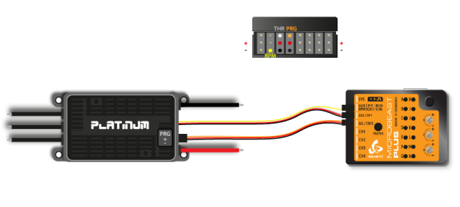
Wenn die Telemetrie verwendet wird, muss der Motorsteller am Anschluss [DI1] angesteckt werden, nicht bei [CH5]! Die Leitung mit dem Telemetrie-Signal wird stattdessen bei [CH5] angesteckt.
Hobbywing® Platinum (V4/V5)
Connect the control wire of your Hobbywing® ESC to port [DI1]. Connect the programming port of your Hobbywing® ESC to port [CH5] using a standard servo wire with male servo plugs on each end.
If needed you can connect the yellow wire for measuring the motor speed to the RPM input at MICROBEAST PLUS. The motor speed signal can be used for the internal governor function of MICROBEAST PLUS. For telemetry transmission it is not necessary as the data will be included in the telemtry signal!
- Smaller Hobbywing® Platinum models (Platinum 60 and 80) do not measure current. Here displayed current and consumed capacity will stay "0.00". However, you can use the displayed battery voltage to estimate the maximum flight time of the model and to effectively prevent a deep discharge of the battery, i. e. by setting a low voltage alarm in your radio.
- Hobbywing® Platinum V3 ESC don't supply any telemtry output. Anyhow, you can connect the motor speed cable as shown above to MICROBEAST PLUS. Then you can display motor speed/headspeed on your radio at least!
Kontronik JIVE
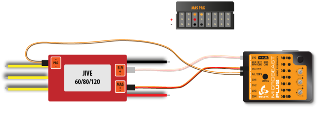
Older Kontronik® JIVE controllers come with a 3-pin debug connector that is normally used to program the motor controller by the use of a jumper wire. However, this connection also outputs some basic information about the motor controller and battery, which can be used for telemetry purpose.
Please note that this is not an official telemetry connection and the data may be inaccurate or not available at all. This depends heavily on the firmware of the ESC which we can't influence.
To connect MICROBEAST PLUS with your JIVE ESC you need a special type of wire. As shown below, the telemetry signal pin is the middle pin of the debug connector. The outer pin is common ground. On MICROBEAST PLUS side you must connect the signal wire to the upper pin of port [CH5] and the common ground to the lowest pin (=minus). You mustn't connect anything to the middle pin (=voltage) of port [CH5]!
Connect the control wire (MASTER port) of your KONTRONIK® ESC to port [DI1]. If needed you can connect the additional power output (SLAVE port) to the [SYS] port of MICROBEAST PLUS.
Please be very careful when connecting your ESC with MICROBEAST PLUS. The voltage pins of [CH5] mustn't be connected with the debug port of your JIVE ESC. Make sure your wiring looks as shown above and make sure to connect the plugs correctly on each side. Do not interchange the sides of the wire. You can heavily damage your MICROBEAST PLUS or your ESC if not following these instructions properly!
Kontronik JIVE PRO/KOSMIK
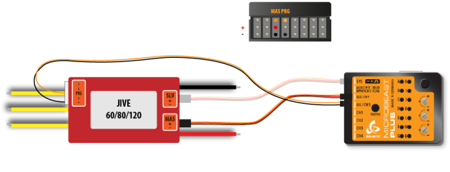
The Kontronik® JIVE PRO/Kosmik controllers comes with a 5-pin connector that is normally used to program the motor controller by the use of a jumper wire. Since firmware version 1.10 Kontronik® added a generic telemetry data output to this connection. Please make sure your JIVE PRO/Kosmik is updated to the latest version.
To connect MICROBEAST PLUS with your JIVE PRO/Kosmik ESC you need a special type of wire. As shown below, the telemetry signal pin is the middle pin of the 5-pin connector. The most inner pin is common ground. On MICROBEAST PLUS side you must connect the signal wire to the upper pin of port [CH5] and the common ground to the lowest pin (=minus). You mustn't connect anything to the middle pin (=voltage) of port [CH5]!
Connect the control wire (MASTER port) of your KONTRONIK® ESC to port [DI1]. If needed you can connect the additional power output (SLAVE port) to the [SYS] port of MICROBEAST PLUS.
Please be very careful when connecting your ESC with MICROBEAST PLUS. The voltage pins of [CH5] mustn't be connected with the telemetry port of your JIVE PRO/Kosmik ESC. Make sure your wiring looks as shown above and make sure to connect the plugs correctly on each side. Do not interchange the sides of the wire. You can heavily damage your MICROBEAST PLUS or your ESC if not following these instructions properly!
Scorpion® Tribunus
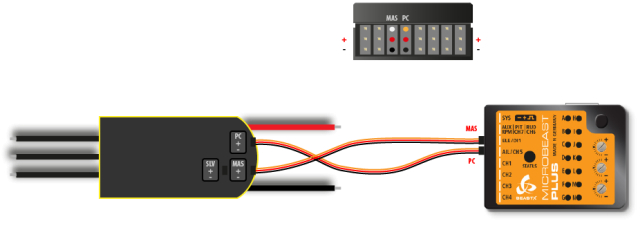
Connect the control wire (MASTER) of your Scorpion® ESC to port [DI1]. Connect the programming port (PC) of your Scorpion® ESC to port [CH5] using a standard servo wire with male servo plugs on each end.
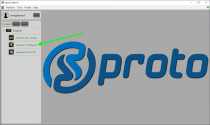
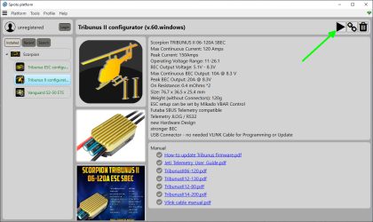
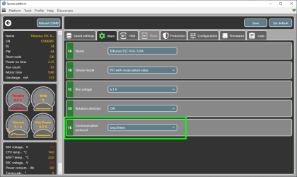
To enable telemetry you must programm your Scorpion® ESC with the supplied Sproto plattform. Please set parameter 1E - communication protocol to "UnSc". For further assistance please read the manual for your ESC or contact the manufacturer of your ESC.
