SETUP MENU K - Cyclic throw
At SETUP MENU point K we adjust the internal servo throw so that MICROBEAST ULTRA has a reference on how far it must move the servos when controlling the helicopter. To set the throw, you align one rotorblade on the longitudinal axis (in parallel to the tail boom) and measure the cyclic pitch with a digital pitch gauge on this rotorblade. (You can do this from the front or from the rear!)

|

|
Initially you should see 0 degrees of pitch now (in case you did setup the trimming at SETUP MENU point J properly!). Then you switch to the adjustment position. The system will give some amount of pitch which you measure again. This time you should see 6.0 degrees (+ or - is not of importance). If not, increase or decrease the swash throw accordingly.
The color of the Status LED gives some indication whether you rotorhead geometry is well suited for flybarless usage or not. Ideally the Status LED on the device should be blue when in 6.0 degress position. If it isn't, this means your servo movements cause very much pitch deflection on the rotorhead. This can be bad for the performance as the system may tend to oversteer and overreact very easily. If you have problem with finding correct gain settings or overcompensation later in flight, the cause may be found here. To solve this you can change geometry by moving the linkage balls on the servo horns closer to the servo center.
| Status-LED | Cyclic throw |
| purple | not good |
| red | OK |
| blue | perfect! |
Adjustment on the device
Initially the Status LED will be off, the swashplate will be leveled and rotorblades will have 0 degrees of pitch. Attach your pitch gauge to the rotorblade or blade grip, calibrate it to 0 degrees and then tap the rudder stick once. This will move the rotorblades into measuring position. Now check the pitch gauge. We want to see exactly +-6.0 degrees. By aileron input you can increase/decrease the amount of pitch (left = decrease, right = increase) until you have reached +-6.0 degrees (the sign/direction of pitch is not of importance). You can switch back and forth between measuring and zero position as often as you like. When done tap the button to proceed to the next menu point.
Setup with StudioX app
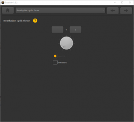
Initially the swashplate will be leveled and rotorblades will have 0 degrees of pitch when the cyclic throw adjustment screen opens. Attach your pitch gauge at the rotorblade or blade grip, calibrate it to 0.0 degrees and then click the Measure button. This will move the rotorblade into measuring position. Now check the pitch gauge, we want to see exactly +-6.0 degrees. Increase/decrease the throw value with the + and - buttons or the dial until the pitch is adjusted correctly. You can switch back and forth between measure and zero position as often as you like.
Measuring pitch without pitch gauge
If your helicopter is too small for attaching a digital pitch gauge or simply in case you haven't got one, you can use a little trick to measure the pitch anyway. You can calculate the angle from the distance the rotor blades move from zero position. Actually this is not as accurate as measuring the pitch with a digital pitch gauge but it's better than nothing. All you need for this is a ruler and and a good eye. First you need to know the length of the rotorblades from the bolt hole to the outer edge. Usually this matches the specified rotor blade length of the manufacturer. Then you align the rotorhead with the longitudinal axis of the helicopter and fold both rotorblades to one side (as this will put heavy load on the servos it is not recommended use this method on large helicopters with heavy blades!). Now hold your ruler to the blades and mark the zero position (or measure the distance from ground to the rotor blades). Then when you switch to adjustment position, the rotorblades will move up or down a few centimetres. The distance travelled can be transfered into degrees of blade pitch using the mathematical formula of sinus. Or the other way round you can calculate how far you rotorblades must move in order to get 6.0 degrees of blade pitch.
Enter blade length in millimeters
