Manuals:BXFbl:Governor/de: Difference between revisions
Shornstein (talk | contribs) No edit summary |
Shornstein (talk | contribs) No edit summary |
||
| (16 intermediate revisions by the same user not shown) | |||
| Line 10: | Line 10: | ||
<br /> | <br /> | ||
Zur Einrichtung der Governor-Funktion bietet das MICROBEAST PLUS/ULTRA ein spezielles Menü. Dieses GOVERNOR MENÜ wird am Ende des SETUP MENÜS angehängt, falls die Governor-Funktion bei SETUPMENÜ PUNKT N aktiviert wird. Die Einstellpunkte des GOVERNOR MENÜ kommen dann nach SETUPMENÜ PUNKT N. Um später in das Governor Menü zu kommen, um eine bestimmte Einstellung zu ändern, muss also das SETUPMENÜ geöffnet werden, und dann 14 mal auf den Knopf gedrück werden, um die SETUPMENÜ Punkte zu überspringen. Alternativ kannst Du die GOVERNOR-Einstellungen über die StudioX-App oder über das Telemetriemenü einer JETI Fernsteuerung oder OPENTX/EDGETX Fernsteuerung mit CRSF-Telemetrie aufrufen. | |||
<br /> | <br /> | ||
<br /> | <br /> | ||
<html> <!-- assumes $wgRawHtml = true; safer alternatives exist --> | <html> <!-- assumes $wgRawHtml = true; safer alternatives exist --> | ||
<style> | <style> | ||
| Line 24: | Line 21: | ||
width: 130px; | width: 130px; | ||
} | } | ||
table#overview tr td:nth-child(3), | |||
table#overview tr td:nth-child(3), | |||
table#overview tr td:nth-child(4), | table#overview tr td:nth-child(4), | ||
table#overview tr td:nth-child(5), | table#overview tr td:nth-child(5), | ||
| Line 38: | Line 33: | ||
</style> | </style> | ||
</html> | </html> | ||
'''GOVERNOR MENÜ Übersicht''' | |||
'''GOVERNOR | |||
{| class="wikitable" id="overview" style="text-align: center; background-color: #F9DDCC; border: solid #999999 2px;" | {| class="wikitable" id="overview" style="text-align: center; background-color: #F9DDCC; border: solid #999999 2px;" | ||
! style="color:white; text-align: left; background-color: #F18308 ;" | | ! style="color:white; text-align: left; background-color: #F18308 ;" | Menü | ||
! style="color:white; background-color: #F18308 ;" | | ! style="color:white; background-color: #F18308 ;" | Beschreibung | ||
! style="color:white; background-color:black;" | | ! style="color:white; background-color:black;" | aus | ||
! style="color:white; background: linear-gradient(to right, #CC66CC, black, #CC66CC);" | | ! style="color:white; background: linear-gradient(to right, #CC66CC, black, #CC66CC);" | blinkt violett | ||
! style="color:white; background-color:#CC66CC;" | | ! style="color:white; background-color:#CC66CC;" | violett | ||
! style="color:white; background: linear-gradient(to right, #FF3300, black, #FF3300);" | | ! style="color:white; background: linear-gradient(to right, #FF3300, black, #FF3300);" | blinkt rot | ||
! style="color:white; background-color:#FF3300;" | | ! style="color:white; background-color:#FF3300;" | rot | ||
! style="color:white; background: linear-gradient(to right, #0066FF, black, #0066FF);" | | ! style="color:white; background: linear-gradient(to right, #0066FF, black, #0066FF);" | blinkt blau | ||
! style="color:white; background-color:#0066FF;" | | ! style="color:white; background-color:#0066FF;" | blau | ||
! style="color:white; background: linear-gradient(to right, #FF3300, black, #0066FF);" | red/blue | ! style="color:white; background: linear-gradient(to right, #FF3300, black, #0066FF);" | red/blue | ||
|- style="font-size: 80%;" | |- style="font-size: 80%;" | ||
| style="font-size: 125%;" | '''A''' || style="font-size: 125%;" | [[#A_- | | style="font-size: 125%;" | '''A''' || style="font-size: 125%;" | [[#A_-_Sensor_Test|Sensor Test]] || colspan = "8" style = "background-color: #EAECF0;" | | ||
|- | |- | ||
| '''B''' || [[#B_- | | '''B''' || [[#B_-_Motor_aus|Motor aus]] || colspan = "8" style = "background-color: #EAECF0;" | | ||
|- | |- | ||
| '''C''' || [[#C_- | | '''C''' || [[#C_-_Vollgas|Vollgas]] || colspan = "8" style = "background-color: #EAECF0;" | | ||
|- | |- | ||
| '''D''' || [[#D_- | | '''D''' || [[#D_-_Gaskurven| Gaskurven]] || off || colspan = "1" style = "background-color: #EAECF0;" | || Autorot. || colspan = "1" style = "background-color: #EAECF0;" | || on || colspan = "1" style = "background-color: #EAECF0;" | || Full thr. || colspan = "1" style = "background-color: #EAECF0;" | | ||
|- | |- | ||
| '''E''' || [[#E_- | | '''E''' || [[#E_-_Teilungsfaktor | Teilungsfaktor ]] || 1 || 2 || 3 || 4 || 5 || 6 || 7 || colspan = "1" style = "background-color: #EAECF0;" | | ||
|- | |- | ||
| '''F''' || [[#F_- | | '''F''' || [[#F_-_Untersetzung | Untersetzung]] || custom || 8|| 9 || 10 || 11 || 12 || 13 || 14 | ||
|- | |- | ||
| '''G''' || [[#F_- | | '''G''' || [[#F_-_Untersetzung | Untersetzung]] || custom || +0.00 || +0.20 || +0.40 || +0.60 || +0.80 || colspan = "2" style = "background-color: #EAECF0;" | | ||
|- | |- | ||
| '''H''' || [[#F_- | | '''H''' || [[#F_-_Untersetzung | Untersetzung]] || custom || +0.00 || +0.05 || +0.10 || +0.15 || colspan = "3" style = "background-color: #EAECF0;" | | ||
|} | |} | ||
<br /> | <br /> | ||
<br /> | <br /> | ||
=Einbau der Hardware= | |||
=Hardware | Damit der Drehzahlregler von MICROBEAST PLUS/ULTRA verwendet werden kann, muss das System die Motordrehzahl erfassen können. Dies erfolgt mit einem Drehzahlsensor, der an den Sensoreingang vom MICROBEAST PLUS/ULTRA angesteckt wird. Bei Modellen mit Verbrennungsmotor werden üblicherweise Sensoren verwendet, welche die Drehzahl magnetisch oder optisch ermitteln. Diese Sensoren werden an Kurbelwelle oder Kupplungsglocke montiert und registrieren hier die Anzahl der Motorumdrehungen. Bei Elektromotoren kann die Motordrehzahl elektronisch anhand der Felddrehzahl des Motors ermittelt werden. Hierzu wird ein Phasensensor (z.B. BXA76013) an eine oder zwei der Motorphasen angeschlossen. Einige Motorsteller besitzen auch direkt einen Anschluss für das Drehzahlsignal, so dass kein zusätzlicher Sensor notwendig ist.<br /> | ||
<br /> | <br /> | ||
Wie der Sensor montiert wird, ist der Anleitung vom Sensor bzw. vom Helikopter zu entnehmen. Das Kabel mit dem Drehzahlsignal wird mit dem optional erhältlichen Sensor Adapterkabel BXA76401 am Sensoranschluss der seitlichen Steckerleiste vom MICROBEAST PLUS/ULTRA angeschlossen. Über diese Steckerleiste wird der Sensor auch mit Spannung versorgt, falls notwendig. Beachte bitte, dass die Höhe der ausgegebenen Spannung der Versorgungsspannung des MICROBEAST PLUS/ULTRA entspricht!<br /> | |||
<br /> | <br /> | ||
Nachfolgend einige Montage- und Anschlussbeispiele. Wie beschrieben können nahezu alle Arten von Drehzahlsensoren verwendet werden. Leider ist es unmöglich sämtliche Typen auszuprobieren und aufzuzählen. Wende Dich im Zweifel an Deinen Fachhändler um zu erfahren, ob ein bestimmter Sensor in Verbindung mit MICROBEAST PLUS/ULTRA verwendet werden kann.<br /> | |||
<br /> | <br /> | ||
==Elektroantrieb mit externem Phasensensor== | |||
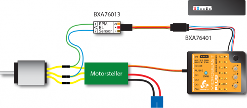
Verbinde die Leitungen des Phasensensors mit zwei beliebigen Phasen des Elektromotors. Es empfiehlt sich die Leitungen an die Steckkontakte des Motorstellers anzulöten. So ist ein späterer Motorausbau z.B. zu Wartungszwecken einfacher. Bei manchen Phasensensoren ist die Verwendung von einer Messleitung ausreichend. Üblicherweise ist das der Fall, wenn der Motorsteller das System über eine BEC - Stromversorgung vom Antriebsakku speißt und dadurch keine galvanische Trennung zwischen Motor- und Empfängerstromkreis vorliegt. Wir empfehlen dennoch stets beide Messleitungen anzuschließen. So ist gewährleistet, dass der Sensor ein möglichst störungsfreies Signal liefert.<br /> | |||
<br /> | <br /> | ||
Der Motorsteller wird am Ausgang [CH5] angesteckt.<br /> | |||
<br /> | <br /> | ||
[[Image: | [[Image:Governormenu_A_ESC_de.png|500px|none]]<br /> | ||
<br /> | <br /> | ||
==Elektroantrieb mit Drehzahlsignal vom Motorsteller== | |||
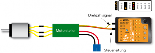
Wenn ein Motorsteller mit Signalleitung für das Drehzahlsignal verwendet wird (z.B. Castle EDGE, Hobbwing Platinum V4, YGE, ...), so kann diese statt an dem seitlichen Sensoranschluss alternativ auch am Anschluss [RPM] an der vorderen Steckerleiste von MICROBEAST PLUS/ULTRA angesteckt werden (unterster Pin des 3-fach Signalanschluss). Drehzahlsensoren können hier aber nicht angeschlossen werden, da an dieser Stiftleiste keine Spannungsversorgung anliegt!<br /> | |||
<br /> | <br /> | ||
[[Image: | Das Kabel zur Ansteuerung des Motorsteller wird am Ausgang [CH5] angesteckt.<br /> | ||
<br /> | |||
[[Image:Governormenu_A_ESC_signalwire_de.png|500px|none]]<br /> | |||
<br /> | <br /> | ||
==Antrieb mit Verbrennungsmotor== | |||
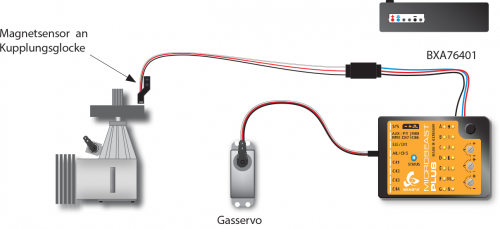
Achte auf polrichtigen Anschluss des Sensors am Adapterkabel BXA76401, da bei Verbrenner-Modellen Sensoren verwendet werden können, die für externe Drehzahlregelsysteme anderer Hersteller konzipiert wurden. Diese haben oft eine spezielle Pinbelegung und die Farben der Anschlusskabel entsprechen u.U. nicht der Norm (beim Align Governor Sensor HE50H22 sind beispielsweise die Kabelfarben vertauscht, hier kennzeichnet rot den Minuspol und schwarz den Pluspol!).<br /> | |||
<br /> | <br /> | ||
[[Image:Governormenu_A_nitro_de.png|500px|none]]<br /> | |||
<br /> | <br /> | ||
= A - Sensor Test = | |||
= A - Sensor | |||
<br /> | <br /> | ||
<br /> | <br /> | ||
= B - Motor aus = | |||
= B - | |||
<br /> | <br /> | ||
<br /> | <br /> | ||
= C - Vollgas = | |||
= C - | |||
<br /> | <br /> | ||
<br /> | <br /> | ||
= D - Gaskurven = | |||
= D - | |||
<br /> | <br /> | ||
<br /> | <br /> | ||
= E - Teilungsfaktor = | |||
= E - | |||
Tap rudder stick to select Signal divider (change LED color).<br /> | Tap rudder stick to select Signal divider (change LED color).<br /> | ||
<br /> | <br /> | ||
= F - Untersetzung = | |||
= F - | |||
Tap rudder stick to select main gear ratio (change LED color). The gear ratio is the sum of menu steps F, G and H.<br /> | Tap rudder stick to select main gear ratio (change LED color). The gear ratio is the sum of menu steps F, G and H.<br /> | ||
<br /> | <br /> | ||
<br /> | <br /> | ||
<br /> | <br /> | ||
Latest revision as of 15:13, 26 March 2025
Was macht die interne Drehzahlregelung?
Die interne Drehzahlregelung ("Governor") des MICROBEAST PLUS/ULTRA steuert das Gas so, dass eine vorgegeben Rotordrehzahl im Flug konstant gehalten wird. Wenn z.B. das Pitch erhöht wird und dadurch die Last auf den Rotor steigt, wird das System mehr Gas geben, um die Motordrehzahl zu halten. Wenn Du andererseits mit dem Heli einen Abschwung fliegst und der Rotor entlastet wird, wird der Motor auftouren, das Gas muss weggenommen werden. Man könnte diese Art von Motorkontrolle auch über die Gaskurven in der Fernsteuerung machen, aber das ist im Ergebnis meist wesentlich ungenauer und aufwändiger. Viel einfacher ist es, dem System mitzuteilen, welche Rotordrehzahl man aktuell fliegen will, und das System kümmert sich dann um den Rest. Es hält die Drehzahl konstant über den gesamten Flug, sogar wenn der Antriebsakku leerer wird oder der Verbrennungsmotor abmagert. Man kann die Governor Funktion mit allen Elektrohelis verwenden, bei denen der Motorcontroller keine eigene, eingebaute "Governor Funktion" (Drehzahlregelung) hat bzw. über einen "Helimodus" verfügt oder wenn diese Funktion nicht zufriedenstellend funktioniert. Wenn Du einen Heli mit Verbrennungsmotor fliegst, brauchst Du keinen zusätzlichen Drehzahlregler mehr kaufen, mit dem MICROBEAST PLUS/ULTRA hast Du dieses Gerät schon mit an Board.
Bitte beachte, dass die Drehzahlregelung nur in Kombination mit einem Summensignal-Empfänger verwendet werden kann! Wenn ein Standard-Empfänger verwendet wird, stehen nicht genügend Anschlüsse zur Verfügung.
Zur Einrichtung der Governor-Funktion bietet das MICROBEAST PLUS/ULTRA ein spezielles Menü. Dieses GOVERNOR MENÜ wird am Ende des SETUP MENÜS angehängt, falls die Governor-Funktion bei SETUPMENÜ PUNKT N aktiviert wird. Die Einstellpunkte des GOVERNOR MENÜ kommen dann nach SETUPMENÜ PUNKT N. Um später in das Governor Menü zu kommen, um eine bestimmte Einstellung zu ändern, muss also das SETUPMENÜ geöffnet werden, und dann 14 mal auf den Knopf gedrück werden, um die SETUPMENÜ Punkte zu überspringen. Alternativ kannst Du die GOVERNOR-Einstellungen über die StudioX-App oder über das Telemetriemenü einer JETI Fernsteuerung oder OPENTX/EDGETX Fernsteuerung mit CRSF-Telemetrie aufrufen.
GOVERNOR MENÜ Übersicht
| Menü | Beschreibung | aus | blinkt violett | violett | blinkt rot | rot | blinkt blau | blau | red/blue |
|---|---|---|---|---|---|---|---|---|---|
| A | Sensor Test | ||||||||
| B | Motor aus | ||||||||
| C | Vollgas | ||||||||
| D | Gaskurven | off | Autorot. | on | Full thr. | ||||
| E | Teilungsfaktor | 1 | 2 | 3 | 4 | 5 | 6 | 7 | |
| F | Untersetzung | custom | 8 | 9 | 10 | 11 | 12 | 13 | 14 |
| G | Untersetzung | custom | +0.00 | +0.20 | +0.40 | +0.60 | +0.80 | ||
| H | Untersetzung | custom | +0.00 | +0.05 | +0.10 | +0.15 | |||
Einbau der Hardware
Damit der Drehzahlregler von MICROBEAST PLUS/ULTRA verwendet werden kann, muss das System die Motordrehzahl erfassen können. Dies erfolgt mit einem Drehzahlsensor, der an den Sensoreingang vom MICROBEAST PLUS/ULTRA angesteckt wird. Bei Modellen mit Verbrennungsmotor werden üblicherweise Sensoren verwendet, welche die Drehzahl magnetisch oder optisch ermitteln. Diese Sensoren werden an Kurbelwelle oder Kupplungsglocke montiert und registrieren hier die Anzahl der Motorumdrehungen. Bei Elektromotoren kann die Motordrehzahl elektronisch anhand der Felddrehzahl des Motors ermittelt werden. Hierzu wird ein Phasensensor (z.B. BXA76013) an eine oder zwei der Motorphasen angeschlossen. Einige Motorsteller besitzen auch direkt einen Anschluss für das Drehzahlsignal, so dass kein zusätzlicher Sensor notwendig ist.
Wie der Sensor montiert wird, ist der Anleitung vom Sensor bzw. vom Helikopter zu entnehmen. Das Kabel mit dem Drehzahlsignal wird mit dem optional erhältlichen Sensor Adapterkabel BXA76401 am Sensoranschluss der seitlichen Steckerleiste vom MICROBEAST PLUS/ULTRA angeschlossen. Über diese Steckerleiste wird der Sensor auch mit Spannung versorgt, falls notwendig. Beachte bitte, dass die Höhe der ausgegebenen Spannung der Versorgungsspannung des MICROBEAST PLUS/ULTRA entspricht!
Nachfolgend einige Montage- und Anschlussbeispiele. Wie beschrieben können nahezu alle Arten von Drehzahlsensoren verwendet werden. Leider ist es unmöglich sämtliche Typen auszuprobieren und aufzuzählen. Wende Dich im Zweifel an Deinen Fachhändler um zu erfahren, ob ein bestimmter Sensor in Verbindung mit MICROBEAST PLUS/ULTRA verwendet werden kann.
Elektroantrieb mit externem Phasensensor
Verbinde die Leitungen des Phasensensors mit zwei beliebigen Phasen des Elektromotors. Es empfiehlt sich die Leitungen an die Steckkontakte des Motorstellers anzulöten. So ist ein späterer Motorausbau z.B. zu Wartungszwecken einfacher. Bei manchen Phasensensoren ist die Verwendung von einer Messleitung ausreichend. Üblicherweise ist das der Fall, wenn der Motorsteller das System über eine BEC - Stromversorgung vom Antriebsakku speißt und dadurch keine galvanische Trennung zwischen Motor- und Empfängerstromkreis vorliegt. Wir empfehlen dennoch stets beide Messleitungen anzuschließen. So ist gewährleistet, dass der Sensor ein möglichst störungsfreies Signal liefert.
Der Motorsteller wird am Ausgang [CH5] angesteckt.

Elektroantrieb mit Drehzahlsignal vom Motorsteller
Wenn ein Motorsteller mit Signalleitung für das Drehzahlsignal verwendet wird (z.B. Castle EDGE, Hobbwing Platinum V4, YGE, ...), so kann diese statt an dem seitlichen Sensoranschluss alternativ auch am Anschluss [RPM] an der vorderen Steckerleiste von MICROBEAST PLUS/ULTRA angesteckt werden (unterster Pin des 3-fach Signalanschluss). Drehzahlsensoren können hier aber nicht angeschlossen werden, da an dieser Stiftleiste keine Spannungsversorgung anliegt!
Das Kabel zur Ansteuerung des Motorsteller wird am Ausgang [CH5] angesteckt.

Antrieb mit Verbrennungsmotor
Achte auf polrichtigen Anschluss des Sensors am Adapterkabel BXA76401, da bei Verbrenner-Modellen Sensoren verwendet werden können, die für externe Drehzahlregelsysteme anderer Hersteller konzipiert wurden. Diese haben oft eine spezielle Pinbelegung und die Farben der Anschlusskabel entsprechen u.U. nicht der Norm (beim Align Governor Sensor HE50H22 sind beispielsweise die Kabelfarben vertauscht, hier kennzeichnet rot den Minuspol und schwarz den Pluspol!).

A - Sensor Test
B - Motor aus
C - Vollgas
D - Gaskurven
E - Teilungsfaktor
Tap rudder stick to select Signal divider (change LED color).
F - Untersetzung
Tap rudder stick to select main gear ratio (change LED color). The gear ratio is the sum of menu steps F, G and H.