EMPFÄNGERMENÜ - Steuerfunktionen
Bei Verwendung eines Summensignal-Empfängers muss definiert werden, welche Steuerkanäle mit welchen Steuerfunktionen verknüpft sind. Beim Summensignal-Empfänger werden die Steuerbefehle als Kette von Daten übertragen. So ist nicht von vorn herein klar, welcher Steuerbefehl zu welchem Steuerknüppel gehört.
Beachte die unten abgebildeten, voreingestellten Funktionszuordnungen und prüfe, ob sie mit der Zuordnung in Deiner Fernsteuerung übereinstimmen (z. B. über den Servomonitor der Steuerung). Wenn Du eine abweichende Zuordnung hast, kannst Du die Zuordnung für das MICROBEAST ULTRA unter EMPFÄNGERMENÜ Punkt B und den nachfolgenden Punkten einlernen. Andernfalls kannst Du die angegebene Zuordnung durch einen Knopfdruck übernehmen.
Einstellung am Gerät
Falls noch nicht geschehen, öffne das EMPFÄNGERMNEÜ und starte die Suche nach dem Fernsteuersystem bei Einstellpunkt A. Im Anschluss springt das System automatisch zu Punkt B.
Wenn die Status-LED rot leuchtet, dann wurden entweder zwei oder mehr Kanäle am Sender betätigt oder das Steuersignal vom Empfänger wurde ganz unterbrochen. Hier nochmals genau die Sendereinstellung bzw. den Servomonitor am Sender prüfen und sicherstellen, dass der Empfänger korrekt angeschlossen ist.
Default function assignment
Refer to the tables at the bottom and identify the column that represents your receiver type. Check if your radio transmits the channels in the given order, respectively each stick function on the radio is using the specified channel number. To know the channel assignment of your transmitter you can check the user manual of the transmitter or look at the servo monitor of the transmitter. In order to load the preset channel assignment hold down the button for at least 2 seconds and release. The yellow Menu-LED will immediately jump to Menu Point K or one of the following.
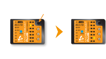 |
| Push and hold the button at Menu Point B to load the preset function assignment |
Manual function assignment
In case the function ordering of your radio system differs from the given tables below, you have to manually assign the channels/functions step by step. This is done by simply actuating the appropriate function on your transmitter at each of the Menu Points B, C, D and so on. Each menu point represents one control function.
When you move the stick/move the channel on the transmitter, the Status LED flashes blue in order to indicate the channel has been detected. It is important that only one channel moves on the radio when the requested function is activated. Otherwise MICROBEAST ULTRA can't recognize the channel movement. The Status LED will flash in red color in this case! If you have moved the wrong stick/switch, just move the correct one afterwards. MICROBEAST ULTRA remembers only the last function that was operated and confirmed with flashing blue Status LED!
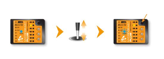 |
| Move the collective at Menu Point B, then push the button when Status LED flashes |
After teaching each function, briefly press the button to save the assignment and to skip to the next function. Once a channel was assigned, it is no longer available and is ignored by MICROBEAST ULTRA for the remaining process! Thus, after learning of the collective pitch function at Menu Point B you can enable the throttle function (remove throttle hold) and teach the throttle channel later at Point G by re-operating the thrust stick there. The collective pitch channel no longer be considered as this channel has already been assigned previously.
The first 6 functions must be assigned as they are necessary for the basic flight control and the button remains locked until you operate a new control function. The other functions are optional to assign and can be skipped. If special features like AttitudeControl or Governor are not installed on your device, the specific menu points for assignment will not be accessible at all!
- The assignment for Aux/CH6 Output at Menu Point H can be skipped by pressing the button without teaching a channel for this function in case it is not used. CH6 may then be used for a 4th swash plate servo if necessary.
- Likewise, the assignment of the channel for the Governor can be skipped in case it is not needed or if you don‘t want to control the governor with a separate channel, e. g. if your transmitter does not provide enough free channels. If needed, the Governor function is then controlled from the throttle channel. When used in an electric model the Governor always is controlled by the throttle channel. Here you can skip Menu Point I, as an assignment will have no effect.
- Finally at Menu Point J you have to assign the channel that is used to engage the AttitudeControl/rescue stabilization (only when you've installed the this feature on your device). Again, this can be skipped if not needed, if you don‘t want to use a separate channel, or in case you haven't enough free channels left. Please see the section about using AttitudeControl for further details.
| Menu point | Function |
|---|---|
| B | Collective |
| C | Aileron |
| D | Elevator |
| E | Rudder |
| F | Tail gyro/Bank switch |
| G | Throttle [CH5] |
| H | Aux Output [CH6] |
| I | Governor control (nitro only) |
| J | AttitudeControl gain |
Setup with StudioX
In StudioX open Control Setup and start the receiver Scan. When this was successful a dialog will appear asking for what to do next.
Default function assignment
Refer to the tables at the bottom and identify the column that represents your receiver type. Check if your radio transmits the channels in the given order, respectively each stick function on the radio is using the specified channel number. To know the channel assignment of your transmitter you can check the user manual of the transmitter or look at the servo monitor of the transmitter. If the assignment on your radio matches the preset functions, simply choose Use default from the dialog.
Manual function assignment
In case the function ordering of your radio system differs from the given tables below, you have to manually assign the channels/functions step by step. This is done by simply actuating the appropriate function on your transmitter at each of the Menu Points B, C, D and so on. Each menu point represents one control function. When you're ready, click Teach in the "New receiver detected!" dialog and start with function assignment at Menu Point B.
- When you move the control stick/change the channel output on the transmitter, the Status LED will flash in blue color when the channel has been detected and the channel number will appear in the display. The setup procedure will jump to the next function assignment immediately.
- It is important that only one channel moves on the radio when the requested function is activated. Otherwise MICROBEAST ULTRA can't recognize the movement. The Status LED will flash red in this case!
- Once a channel was assigned, it is no longer available and is ignored by MICROBEAST ULTRA for the remaining process. So after learning the collective pitch function at Menu Point B, you can enable the throttle function (remove throttle hold) to teach the throttle channel at Menu Point G with the thrust stick. The collective pitch channel will no longer be considered as this channel has been assigned already.
<img class="ios" src="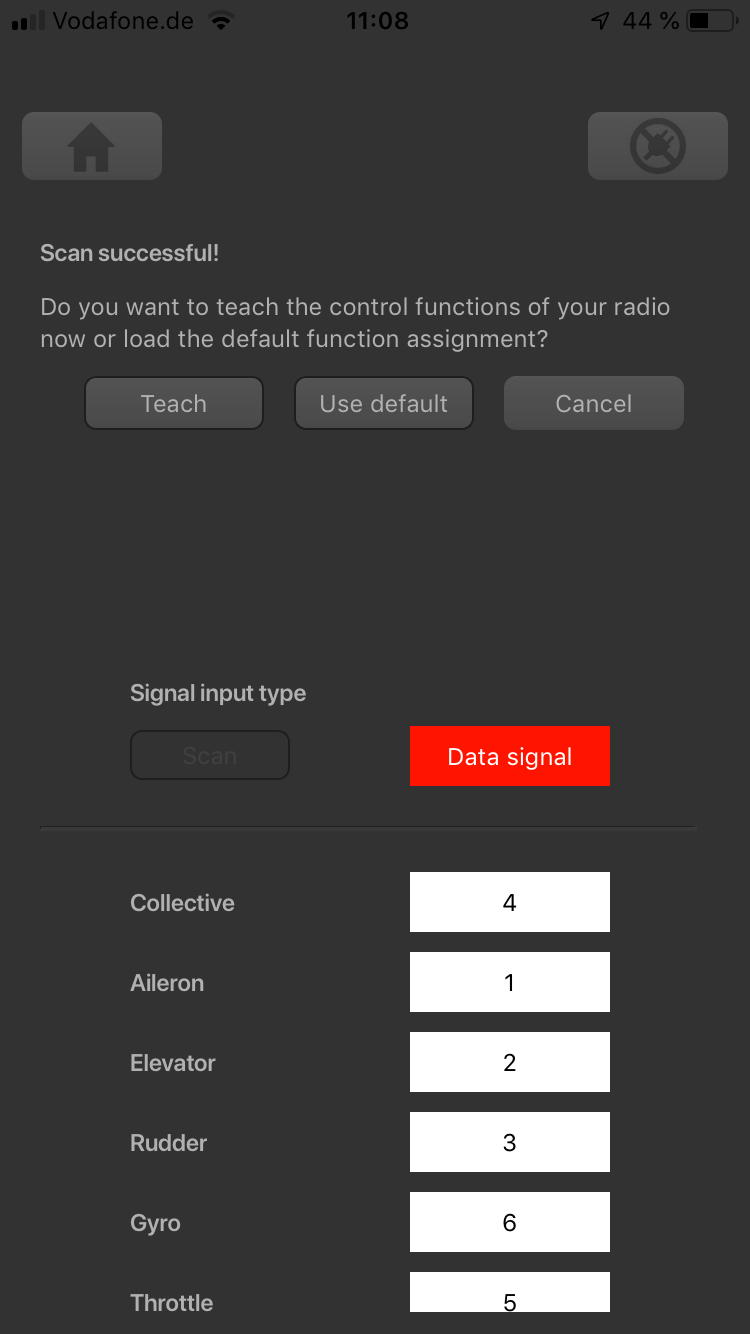
<img class="ios" src="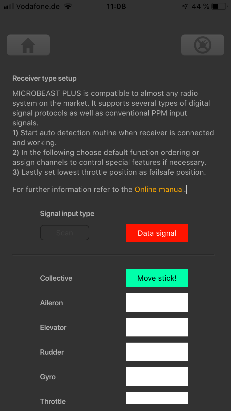
<img class="ios" src="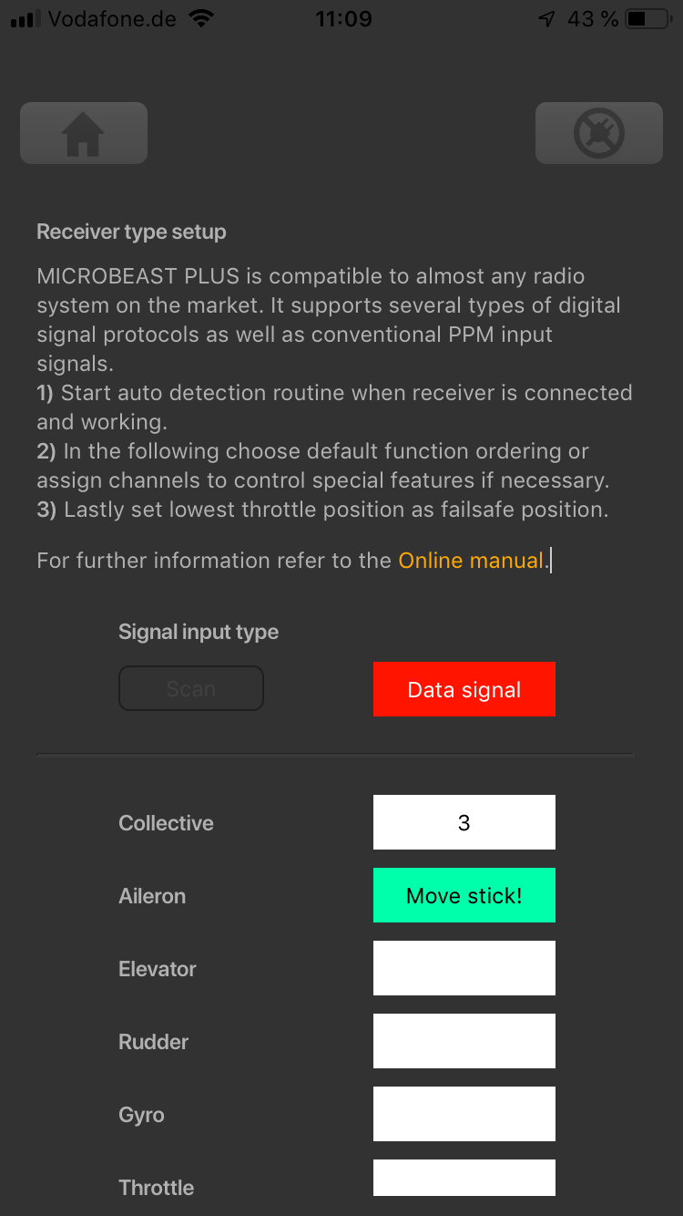
<img class="ios" src="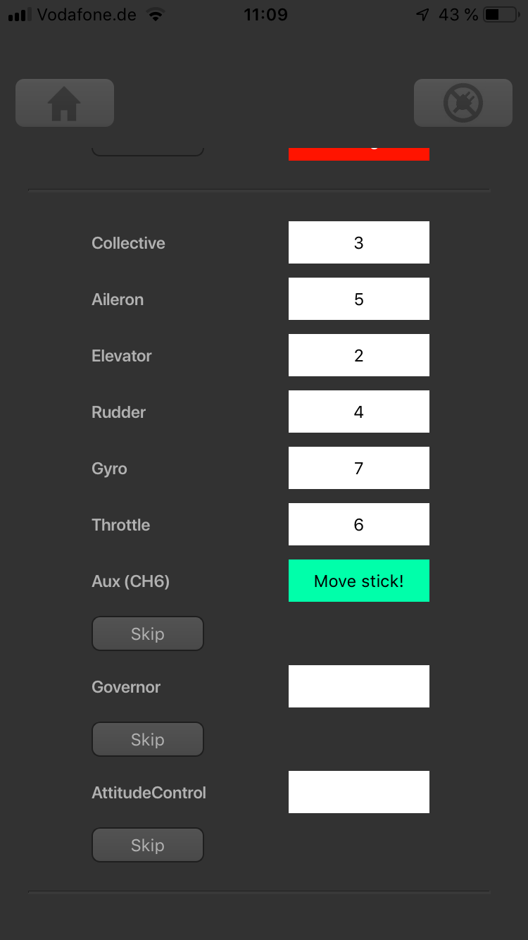
<img class="ios" src="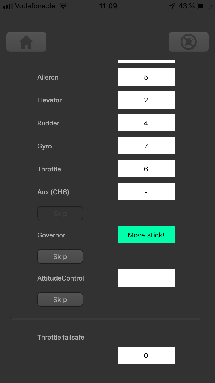
The first 6 functions must be assigned as theses are necessary for the basic flight control. The other functions are optional and can be skipped. If special features like AttitudeControl or Headspeed Governor are not installed on your device, the specific Menu Points will not be shown at all.
- The assignment for Aux [CH6] Output can be skipped by pressing the "Skip" button without teaching a channel for this function in case it is not used. CH6 may then be used for a 4th swash plate servo if necessary.
- Likewise, the assignment of the channel for the Governor can be skipped in case it is not needed or if you don‘t want to control the governor with a separate channel, e. g. if your transmitter does not provide enough free channels. If needed, the Governor function is then controlled from the throttle channel. When used in an electric model the Governor always is controlled by the throttle channel. Here you can skip Menu Point I, as an assignment will have no effect.
- Finally, you can assign the channel that is used to engage the AttitudeControl/rescue stabilization (only available you've installed the PROEDITION Upgrade on your device). Again, this can be skipped if not needed, if you don‘t want to use a separate channel, or in case you haven't enough free channels left. Please see the section about using AttitudeControl for further details.
Preset function assignments
Spektrum® remote satelite or SRXL/SRXL2 receiver
| THR | AIL | ELE | RUD | GER | PIT | AX2 | AX3 |
| Throttle [CH5] | Aileron | Elevator | Rudder | Gyro gain | Pitch | Aux [CH6]* | Governor (nitro) |
JR® RJ01 DMSS remote satellite
| THR | AIL | ELE | RUD | GER | PIT | AX2 | AX3 |
| Throttle [CH5] | Aileron | Elevator | Rudder | Gyro gain | Pitch | Aux [CH6]* | Governor (nitro) |
PPM serial signal (SPPM)
| 1 | 2 | 3 | 4 | 5 | 6 | 7 | 8 |
| Pitch | Aileron | Elevator | Rudder | Aux [CH6]* | Throttle [CH5] | Gyro gain | Governor (nitro) |
Futaba® SBus/SBus2 and FRSky® F.Port
| 1 | 2 | 3 | 4 | 5 | 6 | 7 | 8 |
| Aileron | Elevator | Throttle [CH5] | Rudder | Gyro gain | Pitch | Aux [CH6]* | Governor (nitro) |
Multiplex® SRXL, JR® XBUS Mode B, JETI® UDI
| 1 | 2 | 3 | 4 | 5 | 6 | 7 | 8 |
| Aileron | Elevator | Rudder | Pitch | Throttle [CH5] | Gyro gain | Aux [CH6]* | Governor (nitro) |
Graupner® HOTT SUMD
| 1 | 2 | 3 | 4 | 5 | 6 | 7 | 8 |
| Pitch | Aileron | Elevator | Rudder | Aux [CH6]* | Throttle [CH5] | Gyro gain | Governor (nitro) |
Jeti® EXBUS
| 1 | 2 | 3 | 4 | 5 | 6 | 7 | 8 |
| Throttle [CH5] | Aileron | Elevator | Pitch | Rudder | Gyro gain | Aux [CH6]* | Governor (nitro) |
ALIGN®/FlySky® iBus
| 1 | 2 | 3 | 4 | 5 | 6 | 7 | 8 |
| Aileron | Elevator | Throttle [CH5] | Rudder | Gyro gain | Pitch | Aux [CH6]* | Governor (nitro) |
* Modified assignment with PROEDITION firmware
When using the PROEDITION Firmware upgrade by default the channel for function Aux [CH6] will be used to control the AttidudeControl gain. The control for Aux [CH6] will be moved to channel 9 (or AX4 for Spektrum® radios).
Please note: When you don't want to use a separate channel to control the AttitudeGain or when your radio doesn't have a sufficient amount of output channels, you have to skip the assignment for the AttitudeControl function manually!
