Fernsteuerempfänger
Zur Ansteuerung des MICROBEAST PLUS kann eine Vielzahl unterschiedlicher Empfängertypen verwendet werden. Nachfolgend werden sämtliche Anschlussmöglichkeiten und Arten von Empfängern gezeigt.
Standard Empfänger
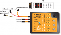
Bei Empfängern mit herkömmlichen (Servo-)Anschlüssen wird das MICROBEAST ULTRA über 5 einzelne Steuerleitungen angesteckt. Über jede dieser Leitungen wird jeweils eine Steuerfunktion vom Fernsteuersender an das System übertragen. Die Zuordnung der Steuerfunktionen am MICROBEAST ULTRA ergibt sich aus der Reihenfolge, in der die Stecker am Empfänger angesteckt werden. Es gibt folgende 5 Funktionen: Roll, Nick, Heck (Gieren), Pitch und Kreisel-Wirkstärke (Gyro gain). Um die Kanalbelegung des Fernsteuerempfängers zu erfahren, schau in die Anleitung des Senders oder prüfe die Belegung anhand der Servomonitors der Fernsteueranlage.
|
Die Abbildung für Spektrum® und Futaba® Empfänger ist nur beispielhaft. Das MICROBEAST ULTRAkann mit allen Fernsteuersystemen verwendet werden, nicht nur mit diesen beiden Marken. Entscheidend für die Kanalreihenfolge ist nicht der Empfänger, sondern die Belegung der Steuerfunktionen im Sender.

|

|
- Die Anschlusskabel für Heck, Pitch und Kreisel sind reine Signalleitungen ohne Stromzufuhr. Achte darauf, dass sie am Empfänger polungsrichtig angesteckt sind, d.h. die Leitungen müssen auf der Signalseite des Empfängers sein, dort wo die orangefarbenen Drähte der anderen Anschlusskabel liegen.
- Alle 5 Funktionen müssen am Empfänger angesteckt sein. Wenn das nicht der Fall ist, dann wird das MICROBEAST PLUS nicht korrekt initialisieren!
- Das Gasservo/Der Motorsteller wird am Empfänger angesteckt, das MICROBEAST hat mit der Steuerung des Motors nichts zu tun. Daher kann Drehzahlregelfunktion nicht in Kombination mit einem Standard Empfänger verwendet werden, das geht nur mit einem Summensignalempfänger.
Receivers with single wire output
A single-line receiver transmits all control functions over one single connection wire to MICROBEAST PLUS. This is done by packing all channel outputs into a digital data paket or by chaining the signals onto one line.
MICROBEAST ULTRA supports the following systems with telemetry uplink:
- Spektrum® SRXL2
- JETI® EXBUS
- GRAUPNER® HOTT
- FRSKY® F.Port2
- FUTABA® SBUS2
MICROBEAST ULTRA supports the following systems without telemetry:
- Spektrum® DSMX/DSM2 remote receivers and receivers with SRXL output
- Futaba® SBUS
- Multiplex® SRXL
- JR® X-Bus (Mode B)
- Jeti® UDI
- ALIGN® and FlySky® iBus
- any SPPM receiver (serial ppm).
Single wire without telemetry
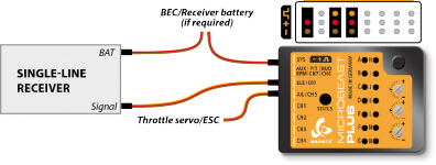
- The single-line connection wire is plugged into the [IO1] input of MICROBEAST ULTRA
- The throttle servo or ESC is connected to the [IO2] output. When using a speed controller with BEC, from here the power will be distributed to receiver and servos.
- You can connect a power supply (second BEC wire, battery) to the [SYS] port and/or to the receiver (in case this has additional servo or battery ports). All servo ports will form a parallel power circuit (except the port [RUD|PIT|AUX]; please do not connect anything here!).
|
| Single-line receiver with additional servo output channels |
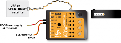
Remote receivers (Spektrum® DSMX/DSM2, JR® DMSS, ALIGN® iBus) can be directly connected to the white pin board at the side of MICROBEAST ULTRA. Here the receiver will be powered with a stabilized voltage of 3.3 Volts! Voltage is the first pin from the front/right, minus is the second pin from the right, signal is connected at the third pin from the right.
Please note: MICROBEAST ULTRA does not support connecting more than one remote satellite at a time!
|
| JR®/Spektrum® remote satellite connected at side pin board |
Using a remote satellite is only recommended for small rc models (helicopters of 450 size or smaller). Due to the design, one single receiving unit is more prone to radio interference and can result in reduced transmission range!
Single wire with telemetry
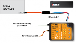
Receivers with bidirectional telemetry uplink (Spektrum® SRXL2, Jeti® EXBUS, FRSKY® F.Port2, FUTABA® SBUS2) must be connected to the pin board at the side of MICROBEAST ULTRA. To connect a receiver with standard servo connectors, i.e. the SPEKTRUM® AR6610T, AR8020T or JETI EXBUS receivers, you need an adapter from servo plug to JST-ZH type. We offer a special adapter if needed - order nr. BXA76403. Voltage is the first pin from the left, signal is connected at the third pin from the left. Minus is the second pin from the front/right.
|
| SRXL2 receiver with standard servo connector and adapter |
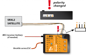
To connect a SRXL2 remote receiver like SPM4650/SPM4651T it is necessary to INTERCHANGE THE WIRES of the supplied 4-pin receiver connector. In this configuration you can directly plug in the receiver without the need for an extra adapter. But be very careful! Make sure plus and minus are placed properly! The signal wire is connected at the fourth pin from the front/right, minus ist second pin from the front/right, voltage (+3.3V) is the first pin from the front/right. On satellite side the signal output is on the outer side, the pin next to it is not used, then we have voltage and on the inner side comes minus.
|
|
| SRXL2 satellite receiver with modified satellite connector | Modified 4-pin SRXL connector |
Never connect the 4-pin receiver connector to MICROBEAST ULTRA without modification and in wrong polarity! This will damage your receiver immediately! Check polarity at least twice before connecting the receiver to MICROBEAST ULTRA . It is up to you to make sure polarity is correct. We do not assume any liability in case you do it wrong.
- When telemetry is not in use, the throttle servo or ESC is connected to the [IO2] output.
- When using a telemetry receiver and an ESC with telemtry data connector, the ESC is connected to the [IO1] output. The data signal of the ESC is connected to [IO2] input. (You will get further information about connecting the speed controller and setting up telemetry on the next page!)
- You can connect a power supply (second BEC wire, battery) to the [SYS] port and/or to the receiver (in case this has additional servo or battery ports). All servo ports will form a parallel power circuit (except the port [RUD|PIT|AUX]; please do not connect anything here!).
When using a big heli with standard size servos it may be insufficient to only provide power at the [SYS] port or receiver. Adding additional power wires is highly recommended! If there are no other ports left to additionally feed in power, we recommend using the MICROBEAST PLUS HD which comes witch an additional high power input. This reduces wiring resistance and serves todays demands for a robust servo power supply.