Manuals:MBPlusFblV52:Receiver M: Difference between revisions
Shornstein (talk | contribs) Created page with "<translate> {{DISPLAYTITLE:Receiver Menu - Telemetry|noerror}} {{TOC_MBPlusV5|Manuals:MBPlusFblV52:Receiver_B/en|Manuals:MBPlusFblV52:Receiver_N/en||2}} __TOC__ <br /> MICROB..." |
Shornstein (talk | contribs) Marked this version for translation |
||
| Line 1: | Line 1: | ||
<translate> | <translate> | ||
<!--T:1--> | |||
{{DISPLAYTITLE:Receiver Menu - Telemetry|noerror}} | {{DISPLAYTITLE:Receiver Menu - Telemetry|noerror}} | ||
{{TOC_MBPlusV5|Manuals:MBPlusFblV52:Receiver_B/en|Manuals:MBPlusFblV52:Receiver_N/en||2}} | {{TOC_MBPlusV5|Manuals:MBPlusFblV52:Receiver_B/en|Manuals:MBPlusFblV52:Receiver_N/en||2}} | ||
| Line 5: | Line 6: | ||
<br /> | <br /> | ||
<!--T:2--> | |||
MICROBEAST PLUS with firmware version 5.4.x or higher offers the possibility of forwarding telemetry data from telemetry capable devices to the receiver, so you can display telemetry data in your transmitter. Since there are no uniform specifications for telemetry data protocols, MICROBEAST PLUS acts as middleware between the systems. A large number of different sensor data can be received, which is converted internally into a uniform format and then forwarded and processed specifically for the receiving remote control system. The typical application is transmitting battery data from the speed controler of an electric model (battery voltage, power draw, power consumption, ESC temperature, ...) to the radio. So the pilot gets detailed insights of battery status and knows when it's time to land.<br /> | MICROBEAST PLUS with firmware version 5.4.x or higher offers the possibility of forwarding telemetry data from telemetry capable devices to the receiver, so you can display telemetry data in your transmitter. Since there are no uniform specifications for telemetry data protocols, MICROBEAST PLUS acts as middleware between the systems. A large number of different sensor data can be received, which is converted internally into a uniform format and then forwarded and processed specifically for the receiving remote control system. The typical application is transmitting battery data from the speed controler of an electric model (battery voltage, power draw, power consumption, ESC temperature, ...) to the radio. So the pilot gets detailed insights of battery status and knows when it's time to land.<br /> | ||
<br /> | <br /> | ||
<!--T:3--> | |||
'''The following speed controllers/sensors can be used as telemetry data source at the moment:''' | '''The following speed controllers/sensors can be used as telemetry data source at the moment:''' | ||
* Hobbywing® Platinum (V4/V5) | * Hobbywing® Platinum (V4/V5) | ||
| Line 16: | Line 19: | ||
<br /> | <br /> | ||
<!--T:4--> | |||
'''The following radio systems can be used to display telemetry data at the moment:''' | '''The following radio systems can be used to display telemetry data at the moment:''' | ||
* Jeti® EXBUS | * Jeti® EXBUS | ||
| Line 21: | Line 25: | ||
<br /> | <br /> | ||
<!--T:5--> | |||
{{QUOTE|Please note that telemetry capability must be purchased as additional feature for your MICROBEAST PLUS. After upgrading the feature you must install the firmware with telemetry support by StudioX software. For devices with PROEDITION firmware it is already included.}}<br /> | {{QUOTE|Please note that telemetry capability must be purchased as additional feature for your MICROBEAST PLUS. After upgrading the feature you must install the firmware with telemetry support by StudioX software. For devices with PROEDITION firmware it is already included.}}<br /> | ||
<br /> | <br /> | ||
=Adjustment on the device= | =Adjustment on the device= <!--T:6--> | ||
After receiver scan and function assignment the Menu Point '''M''' will open, in case you're using a Spektrum® SRXL2 or JETI® EXBUS radio system. If needed you can directly get to this screen without changing your basic radio setup by clicking the button "Telemetry" in overview screen of RECEIVER MENU.<br /> | After receiver scan and function assignment the Menu Point '''M''' will open, in case you're using a Spektrum® SRXL2 or JETI® EXBUS radio system. If needed you can directly get to this screen without changing your basic radio setup by clicking the button "Telemetry" in overview screen of RECEIVER MENU.<br /> | ||
<br /> | <br /> | ||
| Line 50: | Line 55: | ||
<br /> | <br /> | ||
=Setup with StudioX= | =Setup with StudioX= <!--T:7--> | ||
After receiver scan and function assignment an additional setup screen for telemetry will open, in case you're using a Spektrum® SRXL2 or JETI® EXBUS radio system. If needed, also you can directly get to this screen without changing your basic radio setup by clicking the button "Telemetry" in overview screen of RECEIVER MENU.<br /> | After receiver scan and function assignment an additional setup screen for telemetry will open, in case you're using a Spektrum® SRXL2 or JETI® EXBUS radio system. If needed, also you can directly get to this screen without changing your basic radio setup by clicking the button "Telemetry" in overview screen of RECEIVER MENU.<br /> | ||
<br /> | <br /> | ||
| Line 59: | Line 64: | ||
<br /> | <br /> | ||
=Connecting the telemetry sensor/ESC= | =Connecting the telemetry sensor/ESC= <!--T:8--> | ||
<br /> | <br /> | ||
{{WARNING_QUOTE|When using telemetry, the '''control line of the speed controller must be connected to pin [DI1], not [CH5]!''' The cable for the telemetry signal is plugged into [CH5] instead.}}<br /> | {{WARNING_QUOTE|When using telemetry, the '''control line of the speed controller must be connected to pin [DI1], not [CH5]!''' The cable for the telemetry signal is plugged into [CH5] instead.}}<br /> | ||
| Line 65: | Line 70: | ||
<br /> | <br /> | ||
==Hobbywing® Platinum (V4/V5)== | ==Hobbywing® Platinum (V4/V5)== <!--T:9--> | ||
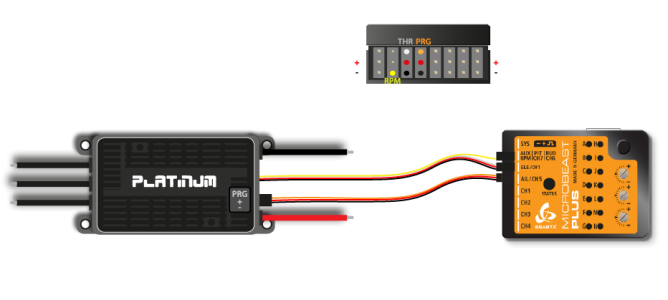
Connect the control wire of your Hobbywing® ESC to port [DI1]. Connect the programming port of your Hobbywing® ESC to port [CH5] using a standard servo wire with male servo plugs on each end.<br /> | Connect the control wire of your Hobbywing® ESC to port [DI1]. Connect the programming port of your Hobbywing® ESC to port [CH5] using a standard servo wire with male servo plugs on each end.<br /> | ||
<br /> | <br /> | ||
| Line 71: | Line 76: | ||
<br /> | <br /> | ||
<!--T:10--> | |||
[[File:Hobbywing.png|x300px|none]] | [[File:Hobbywing.png|x300px|none]] | ||
<br /> | <br /> | ||
| Line 77: | Line 83: | ||
<br /> | <br /> | ||
==Kontronik JIVE== | ==Kontronik JIVE== <!--T:11--> | ||
Older Kontronik® JIVE controllers come with a 3-pin debug connector that is normally used to program the motor controller by the use of a jumper wire. However, this connection also outputs some basic information about the motor controller and battery, which can be used for telemetry purpose.<br /> | Older Kontronik® JIVE controllers come with a 3-pin debug connector that is normally used to program the motor controller by the use of a jumper wire. However, this connection also outputs some basic information about the motor controller and battery, which can be used for telemetry purpose.<br /> | ||
<br /> | <br /> | ||
| Line 96: | Line 102: | ||
<br /> | <br /> | ||
==Kontronik JIVE PRO/KOSMIK== | ==Kontronik JIVE PRO/KOSMIK== <!--T:12--> | ||
The Kontronik® JIVE PRO/Kosmik controllers comes with a 5-pin connector that is normally used to program the motor controller by the use of a jumper wire. Since firmware version 1.10 Kontronik® added a generic telemetry data output to this connection. Please make sure your JIVE PRO/Kosmik is updated to the latest version.<br /> | The Kontronik® JIVE PRO/Kosmik controllers comes with a 5-pin connector that is normally used to program the motor controller by the use of a jumper wire. Since firmware version 1.10 Kontronik® added a generic telemetry data output to this connection. Please make sure your JIVE PRO/Kosmik is updated to the latest version.<br /> | ||
<br /> | <br /> | ||
| Line 113: | Line 119: | ||
<br /> | <br /> | ||
==Scorpion® Tribunus== | ==Scorpion® Tribunus== <!--T:13--> | ||
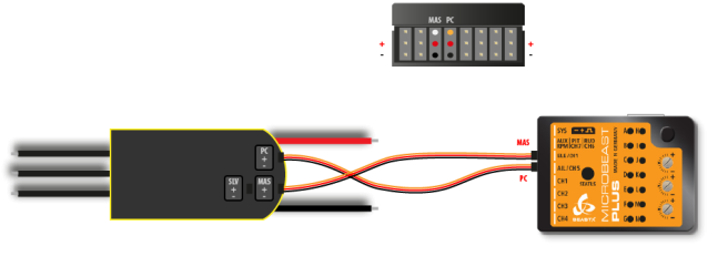
Connect the control wire (MASTER) of your Scorpion® ESC to port [DI1]. Connect the programming port (PC) of your Scorpion® ESC to port [CH5] using a standard servo wire with male servo plugs on each end.<br /> | Connect the control wire (MASTER) of your Scorpion® ESC to port [DI1]. Connect the programming port (PC) of your Scorpion® ESC to port [CH5] using a standard servo wire with male servo plugs on each end.<br /> | ||
<br /> | <br /> | ||
Revision as of 13:41, 6 April 2022
MICROBEAST PLUS with firmware version 5.4.x or higher offers the possibility of forwarding telemetry data from telemetry capable devices to the receiver, so you can display telemetry data in your transmitter. Since there are no uniform specifications for telemetry data protocols, MICROBEAST PLUS acts as middleware between the systems. A large number of different sensor data can be received, which is converted internally into a uniform format and then forwarded and processed specifically for the receiving remote control system. The typical application is transmitting battery data from the speed controler of an electric model (battery voltage, power draw, power consumption, ESC temperature, ...) to the radio. So the pilot gets detailed insights of battery status and knows when it's time to land.
The following speed controllers/sensors can be used as telemetry data source at the moment:
- Hobbywing® Platinum (V4/V5)
- Kontronik® JIVE/PowerJIVE/HeliJIVE
- Kontronik® JIVE Pro/Kosmik
- Scorpion® Tribunus ("UnSc" mode)
- speed sensor connected at RPM input
The following radio systems can be used to display telemetry data at the moment:
- Jeti® EXBUS
- Spektrum® SRXL
Please note that telemetry capability must be purchased as additional feature for your MICROBEAST PLUS. After upgrading the feature you must install the firmware with telemetry support by StudioX software. For devices with PROEDITION firmware it is already included.
Adjustment on the device
After receiver scan and function assignment the Menu Point M will open, in case you're using a Spektrum® SRXL2 or JETI® EXBUS radio system. If needed you can directly get to this screen without changing your basic radio setup by clicking the button "Telemetry" in overview screen of RECEIVER MENU.
To select the connected ESC/telemetry data source move the rudder stick repeatedly in one direction until the Status LED lights in the correct color:
| Status-LED | Telemetry data source |
|---|---|
| off | no telemetry/use RPM signal |
| purple | Hobbywing® Platinum (V4/V5) |
| red flashing | Kontronik® JIVE/PowerJIVE/HeliJIVE |
| red | Kontronik® JIVE Pro/Kosmik |
| blue | Scorpion® Tribunus ("UnSc" mode) |
Setup with StudioX
After receiver scan and function assignment an additional setup screen for telemetry will open, in case you're using a Spektrum® SRXL2 or JETI® EXBUS radio system. If needed, also you can directly get to this screen without changing your basic radio setup by clicking the button "Telemetry" in overview screen of RECEIVER MENU.
Choose the connected ESC/telemetry data source by pressing the corresponding button.
The option Capacity correction can be used to adjust the displayed power consumption in case it does not match the real capacity you see when recharging your battery after the flight. The default value is 100%. If the displayed capacity is lower than the real power consumption increase the value, in case the displayed capacity is too high, decrease this value. Please note this parameter is only effective for Hobbywing® and Kontronik® JIVE (not JIVE PRO/KosmiK) ESCs, as here the power consumption is calculated by MICROBEAST PLUS using the given current draw from the ESC.
Connecting the telemetry sensor/ESC
When using telemetry, the control line of the speed controller must be connected to pin [DI1], not [CH5]! The cable for the telemetry signal is plugged into [CH5] instead.
Hobbywing® Platinum (V4/V5)
Connect the control wire of your Hobbywing® ESC to port [DI1]. Connect the programming port of your Hobbywing® ESC to port [CH5] using a standard servo wire with male servo plugs on each end.
If needed you can connect the yellow wire for measuring the motor speed to the RPM input at MICROBEAST PLUS. The motor speed signal can be used for the internal governor function of MICROBEAST PLUS. For telemetry transmission it is not necessary as the data will be included in the telemtry signal!

- Smaller Hobbywing® Platinum models (Platinum 60 and 80) do not measure current. Here displayed current and consumed capacity will stay "0.00". However, you can use the displayed battery voltage to estimate the maximum flight time of the model and to effectively prevent a deep discharge of the battery, i. e. by setting a low voltage alarm in your radio.
- Hobbywing® Platinum V3 ESC don't supply any telemtry output. Anyhow, you can connect the motor speed cable as shown above to MICROBEAST PLUS. Then you can display motor speed/headspeed on your radio at least!
Kontronik JIVE
Older Kontronik® JIVE controllers come with a 3-pin debug connector that is normally used to program the motor controller by the use of a jumper wire. However, this connection also outputs some basic information about the motor controller and battery, which can be used for telemetry purpose.
Please note that this is not an official telemetry connection and the data may be inaccurate or not available at all. This depends heavily on the firmware of the ESC which we can't influence.
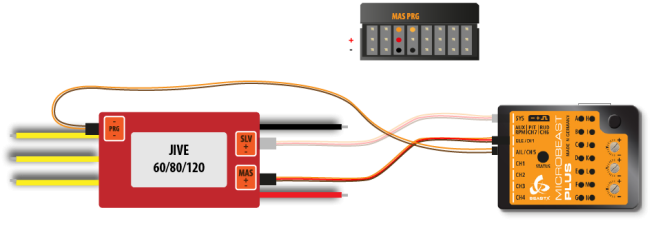
To connect MICROBEAST PLUS with your JIVE ESC you need a special type of wire. As shown below, the telemetry signal pin is the middle pin of the debug connector. The outer pin is common ground. On MICROBEAST PLUS side you must connect the signal wire to the upper pin of port [CH5] and the common ground to the lowest pin (=minus). You mustn't connect anything to the middle pin (=voltage) of port [CH5]!
Connect the control wire (MASTER port) of your KONTRONIK® ESC to port [DI1]. If needed you can connect the additional power output (SLAVE port) to the [SYS] port of MICROBEAST PLUS.
 |
 |
Please be very careful when connecting your ESC with MICROBEAST PLUS. The voltage pins of [CH5] mustn't be connected with the debug port of your JIVE ESC. Make sure your wiring looks as shown above and make sure to connect the plugs correctly on each side. Do not interchange the sides of the wire. You can heavily damage your MICROBEAST PLUS or your ESC if not following these instructions properly!
Kontronik JIVE PRO/KOSMIK
The Kontronik® JIVE PRO/Kosmik controllers comes with a 5-pin connector that is normally used to program the motor controller by the use of a jumper wire. Since firmware version 1.10 Kontronik® added a generic telemetry data output to this connection. Please make sure your JIVE PRO/Kosmik is updated to the latest version.
To connect MICROBEAST PLUS with your JIVE PRO/Kosmik ESC you need a special type of wire. As shown below, the telemetry signal pin is the middle pin of the 5-pin connector. The most inner pin is common ground. On MICROBEAST PLUS side you must connect the signal wire to the upper pin of port [CH5] and the common ground to the lowest pin (=minus). You mustn't connect anything to the middle pin (=voltage) of port [CH5]!
Connect the control wire (MASTER port) of your KONTRONIK® ESC to port [DI1]. If needed you can connect the additional power output (SLAVE port) to the [SYS] port of MICROBEAST PLUS.
Please be very careful when connecting your ESC with MICROBEAST PLUS. The voltage pins of [CH5] mustn't be connected with the telemetry port of your JIVE PRO/Kosmik ESC. Make sure your wiring looks as shown above and make sure to connect the plugs correctly on each side. Do not interchange the sides of the wire. You can heavily damage your MICROBEAST PLUS or your ESC if not following these instructions properly!
Scorpion® Tribunus
Connect the control wire (MASTER) of your Scorpion® ESC to port [DI1]. Connect the programming port (PC) of your Scorpion® ESC to port [CH5] using a standard servo wire with male servo plugs on each end.
 |
To enable telemetry you must programm your Scorpion® ESC with the supplied Sproto plattform. Please set parameter 1E - communication protocol to "UnSc". For further assistance please read the manual for your ESC or contact the manufacturer of your ESC.