GOVERNOR MENÜ A - Sensortest
Adjustment on the device
At GOVERNOR MENU point A there is nothing to adjust. Here you will only get some visual indication to see if the hardware is working so far and in general if there is a usable rpm signal.
Watch out! At this menu point the throttle channel is unlocked. This means you have full control over the speed controller or throttle servo at throttle output [THR].
Be aware that electric motors rotate at high speeds! Keep a safe distance during the function test. We highly recommend to remove the motor from the main gear. However, please observe the manufacturer‘s specifications of the motor. Some motors may not be operated without load. In this case only let the motor run for a short time or let the motor stay attached to the main gear and only remove the main and tail rotor blades (Be careful, increased risk of injury!).
When using an electric model it is necessary to increase the throttle until the motor starts to rotate and the phase sensor or the speed controller outputs a rpm signal. Once the motor is running the Status-LED on the AR7210BX should light up in red color.
Please note that the control range of throttle is crucial! Usually the throttle endpoints of the transmitter are fixed by an initial programming of the speed controller. But also speed controllers exist that require adjusting the servo throw of throttle channel in the transmitter, so that the throttle range is in accordance with the specification of the speed controller. Here you get the possibilty to check whether this setting has been performed correctly. When add a little throttle the motor should start to turn immediately; full speed should be reached when the stick just reaches full throttle position! If the motor turns at the maximum possible speed much earlier or only starts to turn at a very high stick deflection, decrease the travel of throttle channel in the transmitter or repeat the programming of the speed controller. Thus the Governor of the AR7210BX can operate correctly, the motor speed should increase as linear as possible when the stick is moved and there should be no dead zones which the motor speed does not change at.
With a nitro/gas powered helicopter you can simply rotate the clutch or engine crankshaft by hand until the signal generator (magnet or similar) passes the sensor. Whenever the signal generator is within the detection range of the sensor the Status-LED should light up in blue color.
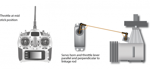
In addition to the function control of the sensor, check the throw setting for the throttle servo in the remote control and adjust if necessary: Set the throttle to mid stick position and attach the servo horn, so that the throttle linkage is at a right angle to the servo horn. Then adjust the length of the linkage according to the instructions of the helicopter, so that it also is positioned perpendicular to the linkage lever at the carburetor. Adjust the lever at the carburetor so that it is opened halfways (note the markings on the carburetor!). Now move the throttle stick towards full throttle and adjust the servo travel in the transmitter accordingly, so that the full throttle position is reached without binding. Lastly move both throttle stick and throttle trim on the transmitter to the „motor off“ position and also adjust the servo travel in that direction until the carburetor is fully closed. If the servo travel must be greatly reduced in both directions, it is recommended that the linkage ball on the servo arm is mounted further in so that the servo can be moved over a wider range. For more information refer to the instruction manual for your helicopter.

If the Status-LED on the AR7210BX does not light up as described please double check the wiring. Particularly pay attention whether the power wires of the sensor are of correct polarity (on some sensors the wire colors do not match the usual standard!). If you have a magnetic sensor check if the magnets are installed with the correct polarity and if they are passing the front of the sensor close enough. Using a crankshaft sensor make sure that the sensor is mounted close enough to the frame accordingly.
Setup with StudioX
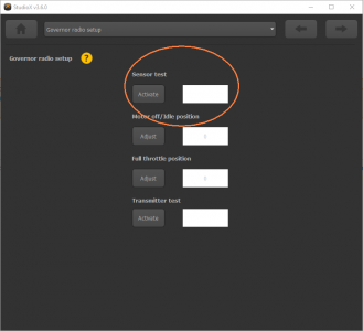
From the overview open the Menu Governor Setup. There go to the sub menu Governor radio setup and "Activate" the Sensor test. The label will light up and red or blue color as described above. With an electric model also you can read the motor speed/head speed in order to verify the setup of main gear ratio and signal divider done at the Governor basic setup. When finished click Exit.
