Difference between revisions of "Manuals:BXFbl:Radio Setup:Standard PPM"
Shornstein (talk | contribs) (Created page with "<translate> <!--T:1--> {{TOC_BXFbl|Manuals:BXFbl:Radio_Setup:FRSKY/en|Manuals:BXFbl:Radio_Setup:SPPM/en||}} {{DISPLAYTITLE:Standard RX Type|noerror}} __TOC__ <!--T:2--> <br /...") |
Shornstein (talk | contribs) (Marked this version for translation) |
||
| Line 15: | Line 15: | ||
<br /> | <br /> | ||
| + | <!--T:16--> | ||
{|cellspacing = "20" | {|cellspacing = "20" | ||
|style="text-align:center;"| [[Image:Standard_RX.png|250px]] | |style="text-align:center;"| [[Image:Standard_RX.png|250px]] | ||
| Line 20: | Line 21: | ||
<br /> | <br /> | ||
| + | <!--T:17--> | ||
Additionally you need a 6th channel for motor control (which is not done by MICROBEAST).<br /> | Additionally you need a 6th channel for motor control (which is not done by MICROBEAST).<br /> | ||
<br /> | <br /> | ||
| Line 29: | Line 31: | ||
<br /> | <br /> | ||
| + | <!--T:18--> | ||
Here we show connection layouts for two common radio brands. Note that this is only an example, you can use any radio system on the market, not only these two brands! Just make sure that you connect the wires to the correct functions as mentioned above.<br /> | Here we show connection layouts for two common radio brands. Note that this is only an example, you can use any radio system on the market, not only these two brands! Just make sure that you connect the wires to the correct functions as mentioned above.<br /> | ||
<br /> | <br /> | ||
| + | <!--T:19--> | ||
{|cellspacing = "20" | {|cellspacing = "20" | ||
|[[Image:Spektrum_RX.png|x100px]] | |[[Image:Spektrum_RX.png|x100px]] | ||
| Line 37: | Line 41: | ||
|}<br /> | |}<br /> | ||
| + | <!--T:20--> | ||
{{QUOTE| | {{QUOTE| | ||
* The wires for rudder, thrust and gyro are all signal wires. Although some have different color, they must be placed on the same receiver side as the the orange wires from roll/aileron and pitch/elevator! | * The wires for rudder, thrust and gyro are all signal wires. Although some have different color, they must be placed on the same receiver side as the the orange wires from roll/aileron and pitch/elevator! | ||
| Line 50: | Line 55: | ||
<br /> | <br /> | ||
| + | <!--T:21--> | ||
You can also use the StudioX app to start receiver scan. In this case open the '''Control''' menu in StudioX and click the '''SCAN''' button in this menu's screen. Please note that other receiver related options are not available when using a Standard receiver. Simply there is nothing else that needs to be set.<br /> | You can also use the StudioX app to start receiver scan. In this case open the '''Control''' menu in StudioX and click the '''SCAN''' button in this menu's screen. Please note that other receiver related options are not available when using a Standard receiver. Simply there is nothing else that needs to be set.<br /> | ||
<br /> | <br /> | ||
Latest revision as of 14:57, 9 April 2024
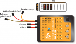
MICROBEAST PLUS and MICROBEAST ULTRA can be used with any conventional receiver that features at least 5 servo output channels. Each control function of MICROBEAST is connected with one channel at the receiver:
- Pitch/elevator
- Roll/aileron
- Rudder/yaw
- Collective/thrust
- Gyro (gain)

|
Additionally you need a 6th channel for motor control (which is not done by MICROBEAST).
Connection scheme
Connect the servo outputs of the receiver to each control function of MICROBEAST PLUS / ULTRA by using one wire for each function. If you don't know which stick controls which channel have a look at your radio's servo monitor, refer to your radios instruction manual or simply connect a servo to test what each output is used for!
Here we show connection layouts for two common radio brands. Note that this is only an example, you can use any radio system on the market, not only these two brands! Just make sure that you connect the wires to the correct functions as mentioned above.

|

|
- The wires for rudder, thrust and gyro are all signal wires. Although some have different color, they must be placed on the same receiver side as the the orange wires from roll/aileron and pitch/elevator!
- You must connect all 5 functions/wires to the receiver. When you don't connect all wires, the system will not finish initialization sequence!
- The throttle servo/speed controller is connected to the receiver's throttle output. So using the Governor function of MICROBEAST PLUS / ULTRA is not possible in combination with a Standard receiver. If needed, please consider using a receiver with digital data output.
- When using AttitudeControl function this can be only controlled from the gyro channel. A separate control channel is not available for the Standard wiring layout. If needed, please consider using a receiver with digital data output.
BEASTX setup
In order to use your receiver you have to scan the input type in the RECEIVER MENU of your BEASTX device. Push and hold the button on your MICROBEAST and power up the device. Menu LED A will flash instantly. Now release the button. Push again to start the scan process. When scan was successful your MICROBEAST will start with init sequence. You can perform basic setup procedure in SETUP MENU when init sequence was completed. For further information about RECEIVER MENU setup, see next section.
You can also use the StudioX app to start receiver scan. In this case open the Control menu in StudioX and click the SCAN button in this menu's screen. Please note that other receiver related options are not available when using a Standard receiver. Simply there is nothing else that needs to be set.
(Picture sys adapter!)