Manuals:BXFbl:Governor: Difference between revisions
Shornstein (talk | contribs) No edit summary |
Shornstein (talk | contribs) Marked this version for translation |
||
| Line 10: | Line 10: | ||
<br /> | <br /> | ||
<!--T:2--> | |||
{{QUOTE|Please note that the Governor function is '''not applicable when a Standard receiver is used'''! There is no option to connect throttle to the flybarless system here.}}<br /> | {{QUOTE|Please note that the Governor function is '''not applicable when a Standard receiver is used'''! There is no option to connect throttle to the flybarless system here.}}<br /> | ||
<br /> | <br /> | ||
<!--T:3--> | |||
To setup the Governor function MICROBEAST PLUS/ULTRA offers a specific menu. This GOVERNOR MENU will be added to the SETUP MENU in case you've activated the Governor function at SETUP MENU POINT N. The GOVERNOR MENU steps will follow SETUP MENU POINT N. You can directly skip over SETUP MENU and access GOVERNOR MENU later by repeatedly pressing the button multiple times when in SETUP MENU. Alternatively you can access GOVERNOR MENU settings using the StudioX app or using the telemetry menu of your JETI radio or OPENTX/EDGETX radio with CRSF telemetry. | To setup the Governor function MICROBEAST PLUS/ULTRA offers a specific menu. This GOVERNOR MENU will be added to the SETUP MENU in case you've activated the Governor function at SETUP MENU POINT N. The GOVERNOR MENU steps will follow SETUP MENU POINT N. You can directly skip over SETUP MENU and access GOVERNOR MENU later by repeatedly pressing the button multiple times when in SETUP MENU. Alternatively you can access GOVERNOR MENU settings using the StudioX app or using the telemetry menu of your JETI radio or OPENTX/EDGETX radio with CRSF telemetry. | ||
<br /> | <br /> | ||
<br /> | <br /> | ||
<!--T:4--> | |||
<html> <!-- assumes $wgRawHtml = true; safer alternatives exist --> | <html> <!-- assumes $wgRawHtml = true; safer alternatives exist --> | ||
<style> | <style> | ||
| Line 25: | Line 28: | ||
} | } | ||
table#overview tr td:nth-child(3), | <!--T:5--> | ||
table#overview tr td:nth-child(3), | |||
table#overview tr td:nth-child(4), | table#overview tr td:nth-child(4), | ||
table#overview tr td:nth-child(5), | table#overview tr td:nth-child(5), | ||
| Line 37: | Line 41: | ||
</html> | </html> | ||
<!--T:6--> | |||
'''GOVERNOR MENU overview''' | '''GOVERNOR MENU overview''' | ||
{| class="wikitable" id="overview" style="text-align: center; background-color: #F9DDCC; border: solid #999999 2px;" | {| class="wikitable" id="overview" style="text-align: center; background-color: #F9DDCC; border: solid #999999 2px;" | ||
| Line 70: | Line 75: | ||
<!--T:7--> | |||
=Hardware installation= | =Hardware installation= | ||
Thus Governor of MICROBEAST PLUS/ULTRA can be used, the system must be able to detect the motor speed. This is done with the help of a rpm sensor that must be attached to the sensor input pin of MICROBEAST PLUS/ULTRA. For models with nitro/gas engines usually sensors are used that determine the speed signal magnetically or optically. These sensors are mounted next to the crankshaft or clutch bell and register the number of engine revolutions here. For electric motors the motor speed can be determined electronically. For this purpose a phase sensor (e.g. BXA76013) is connected to one or two of the motor phases. Some electric speed controllers also offer a direct signal output for the rpm signal, so that no additional sensor is required.<br /> | Thus Governor of MICROBEAST PLUS/ULTRA can be used, the system must be able to detect the motor speed. This is done with the help of a rpm sensor that must be attached to the sensor input pin of MICROBEAST PLUS/ULTRA. For models with nitro/gas engines usually sensors are used that determine the speed signal magnetically or optically. These sensors are mounted next to the crankshaft or clutch bell and register the number of engine revolutions here. For electric motors the motor speed can be determined electronically. For this purpose a phase sensor (e.g. BXA76013) is connected to one or two of the motor phases. Some electric speed controllers also offer a direct signal output for the rpm signal, so that no additional sensor is required.<br /> | ||
| Line 78: | Line 84: | ||
<br /> | <br /> | ||
<!--T:8--> | |||
==Electric drive system with external phase sensor== | ==Electric drive system with external phase sensor== | ||
Connect the motor wires of the phase sensor with any two phases of the electric motor. It is recommended to solder those wires to the plugs of the speed controller. So for maintenance purposes it is easier to remove the motor from the model later. In some cases the use of only one phase wire is sufficient. Usually this is the case when the speed controller powers the system with a BEC thus there is no galvanic isolation between motor and receiver circuit. However, we recommend using both wires in any case! This ensures that the sensor provides an interference-free signal as possible.<br /> | Connect the motor wires of the phase sensor with any two phases of the electric motor. It is recommended to solder those wires to the plugs of the speed controller. So for maintenance purposes it is easier to remove the motor from the model later. In some cases the use of only one phase wire is sufficient. Usually this is the case when the speed controller powers the system with a BEC thus there is no galvanic isolation between motor and receiver circuit. However, we recommend using both wires in any case! This ensures that the sensor provides an interference-free signal as possible.<br /> | ||
| Line 86: | Line 93: | ||
<br /> | <br /> | ||
<!--T:9--> | |||
==Electric drive system with rpm signal output from the speed controller== | ==Electric drive system with rpm signal output from the speed controller== | ||
When a speed controller is used that provides a rpm signal output you can alternatively use the [RPM] sensor input on the front connection board of MICROBEAST PLUS/ULTRA (lowest pin of the tripple signal input). (RPM sensors can‘t be connected here as this pin header does not provide any power supply!) | When a speed controller is used that provides a rpm signal output you can alternatively use the [RPM] sensor input on the front connection board of MICROBEAST PLUS/ULTRA (lowest pin of the tripple signal input). (RPM sensors can‘t be connected here as this pin header does not provide any power supply!) | ||
| Line 93: | Line 101: | ||
<br /> | <br /> | ||
<!--T:10--> | |||
==Combustion drive system (nitro/gas)== | ==Combustion drive system (nitro/gas)== | ||
Particularly when using sensors for combustion engines check for correct polarity of the sensor power supply on the adapter cable BXA76401. Here commonly sensors are used that are designed for governor systems from other manufacturers and therefore have a special pin assignment. In this case the colors of the connecting cables may not follow the norm (The wire colors of the ALIGN governor sensor HE50H22 are swapped for example. Here red denotes the negative and black the positive pole!).<br /> | Particularly when using sensors for combustion engines check for correct polarity of the sensor power supply on the adapter cable BXA76401. Here commonly sensors are used that are designed for governor systems from other manufacturers and therefore have a special pin assignment. In this case the colors of the connecting cables may not follow the norm (The wire colors of the ALIGN governor sensor HE50H22 are swapped for example. Here red denotes the negative and black the positive pole!).<br /> | ||
| Line 100: | Line 109: | ||
<br /> | <br /> | ||
<!--T:11--> | |||
= A - Sensor test mode = | = A - Sensor test mode = | ||
<br /> | <br /> | ||
<br /> | <br /> | ||
<!--T:12--> | |||
= B - Throttle low position = | = B - Throttle low position = | ||
<br /> | <br /> | ||
<br /> | <br /> | ||
<!--T:13--> | |||
= C - Throttle high position = | = C - Throttle high position = | ||
<br /> | <br /> | ||
<br /> | <br /> | ||
<!--T:14--> | |||
= D - Transmitter setup = | = D - Transmitter setup = | ||
<br /> | <br /> | ||
<br /> | <br /> | ||
<!--T:15--> | |||
= E - Signal divider = | = E - Signal divider = | ||
Tap rudder stick to select Signal divider (change LED color).<br /> | Tap rudder stick to select Signal divider (change LED color).<br /> | ||
<br /> | <br /> | ||
<!--T:16--> | |||
= F - Main gear ratio = | = F - Main gear ratio = | ||
Tap rudder stick to select main gear ratio (change LED color). The gear ratio is the sum of menu steps F, G and H.<br /> | Tap rudder stick to select main gear ratio (change LED color). The gear ratio is the sum of menu steps F, G and H.<br /> | ||
<br /> | <br /> | ||
<!--T:17--> | |||
<br /> | <br /> | ||
<br /> | <br /> | ||
</translate> | </translate> | ||
Revision as of 08:21, 25 March 2025
What's a Headspeed Governor?
MICROBEAST PLUS/ULTRA comes with an internal headspeed governor function. This can control the throttle automatically, so that the rotor headspeed of the helicopter stays consistent in flight. I.e. when you add pitch and load the rotor disk, the system will add more throttle in order to prevent from sagging headspeed, when you descend quickly the system on the other hand will have to lower the throttle to prevent from overspeeding. Usually this is what you try to do when using the throttle curves of your transmitter, but this is very inprecise and will not give reproducible results. It's much more convenient to just tell the system what rotor headspeed you want and this will maintain the given head speed for the whole flight, even when batteries go empty or the motor starts to run lean. The governor function can be used with electric heli which doesn't have a governor or "heli mode" built in the speed controler or when the governor function of the speed controller doesn't maintain the headspeed very well. For helis with combustion engine you don't need to buy a separate governor device anymore, with MICROBEAST PLUS/ULTRA you already have it on your heli.
Please note that the Governor function is not applicable when a Standard receiver is used! There is no option to connect throttle to the flybarless system here.
To setup the Governor function MICROBEAST PLUS/ULTRA offers a specific menu. This GOVERNOR MENU will be added to the SETUP MENU in case you've activated the Governor function at SETUP MENU POINT N. The GOVERNOR MENU steps will follow SETUP MENU POINT N. You can directly skip over SETUP MENU and access GOVERNOR MENU later by repeatedly pressing the button multiple times when in SETUP MENU. Alternatively you can access GOVERNOR MENU settings using the StudioX app or using the telemetry menu of your JETI radio or OPENTX/EDGETX radio with CRSF telemetry.
GOVERNOR MENU overview
| Menu | Description | off | purple fl. | purple | red flashing | red | blue flashing | blue | red/blue |
|---|---|---|---|---|---|---|---|---|---|
| A | Sensor test mode | ||||||||
| B | Throttle low position | ||||||||
| C | Throttle high position | ||||||||
| D | Transmitter setup | off | Autorot. | on | Full thr. | ||||
| E | Signal divider | 1 | 2 | 3 | 4 | 5 | 6 | 7 | |
| F | Main gear ratio | custom | 8 | 9 | 10 | 11 | 12 | 13 | 14 |
| G | Main gear ratio | custom | +0.00 | +0.20 | +0.40 | +0.60 | +0.80 | ||
| H | Main gear ratio | custom | +0.00 | +0.05 | +0.10 | +0.15 | |||
Hardware installation
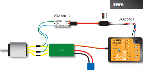
Thus Governor of MICROBEAST PLUS/ULTRA can be used, the system must be able to detect the motor speed. This is done with the help of a rpm sensor that must be attached to the sensor input pin of MICROBEAST PLUS/ULTRA. For models with nitro/gas engines usually sensors are used that determine the speed signal magnetically or optically. These sensors are mounted next to the crankshaft or clutch bell and register the number of engine revolutions here. For electric motors the motor speed can be determined electronically. For this purpose a phase sensor (e.g. BXA76013) is connected to one or two of the motor phases. Some electric speed controllers also offer a direct signal output for the rpm signal, so that no additional sensor is required.
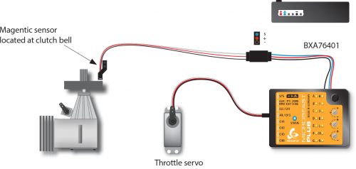
To see how the sensor is mounted in detail please refer to the instruction manual from the sensor or from the helicopter. The wire with the rpm signal is connected to sensor input pin at the sideport of MICROBEAST PLUS/ULTRA by using the optional adapter cable BXA76401. This sideboard also powers the sensor with the supply voltage, if necessary. Note that the height of the supply voltage corresponds to your receiver power supply voltage!
Here are some installation and connection examples. As described virtually all kinds of rpm sensors may be used. Unfortunately it is impossible to try and enumerate all types. If in doubt about whether a particular sensor can be used in conjunction with MICROBEAST PLUS/ULTRA ask your dealer to find out.
Electric drive system with external phase sensor
Connect the motor wires of the phase sensor with any two phases of the electric motor. It is recommended to solder those wires to the plugs of the speed controller. So for maintenance purposes it is easier to remove the motor from the model later. In some cases the use of only one phase wire is sufficient. Usually this is the case when the speed controller powers the system with a BEC thus there is no galvanic isolation between motor and receiver circuit. However, we recommend using both wires in any case! This ensures that the sensor provides an interference-free signal as possible.
The electronic speed controller is plugged into the [CH5] output.

Electric drive system with rpm signal output from the speed controller
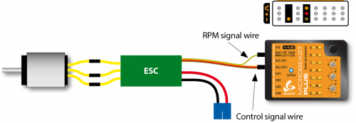
When a speed controller is used that provides a rpm signal output you can alternatively use the [RPM] sensor input on the front connection board of MICROBEAST PLUS/ULTRA (lowest pin of the tripple signal input). (RPM sensors can‘t be connected here as this pin header does not provide any power supply!)
The speed controller‘s signal input wire is plugged into the output [CH5] as usual.

Combustion drive system (nitro/gas)
Particularly when using sensors for combustion engines check for correct polarity of the sensor power supply on the adapter cable BXA76401. Here commonly sensors are used that are designed for governor systems from other manufacturers and therefore have a special pin assignment. In this case the colors of the connecting cables may not follow the norm (The wire colors of the ALIGN governor sensor HE50H22 are swapped for example. Here red denotes the negative and black the positive pole!).

A - Sensor test mode
B - Throttle low position
C - Throttle high position
D - Transmitter setup
E - Signal divider
Tap rudder stick to select Signal divider (change LED color).
F - Main gear ratio
Tap rudder stick to select main gear ratio (change LED color). The gear ratio is the sum of menu steps F, G and H.